
Welding methods and apparatus for batteries

a technology of battery and welding method, applied in the field of coupling methods, can solve the problems greater overall yield, and achieve the effects of reducing variability in joint strength properties, improving process repeatability, and reducing variability

Inactive Publication Date: 2006-10-05
MEDTRONIC INC
View PDF30 Cites 49 Cited by
  • Summary
  • Abstract
  • Description
  • Claims
  • Application Information

AI Technical Summary

Benefits of technology

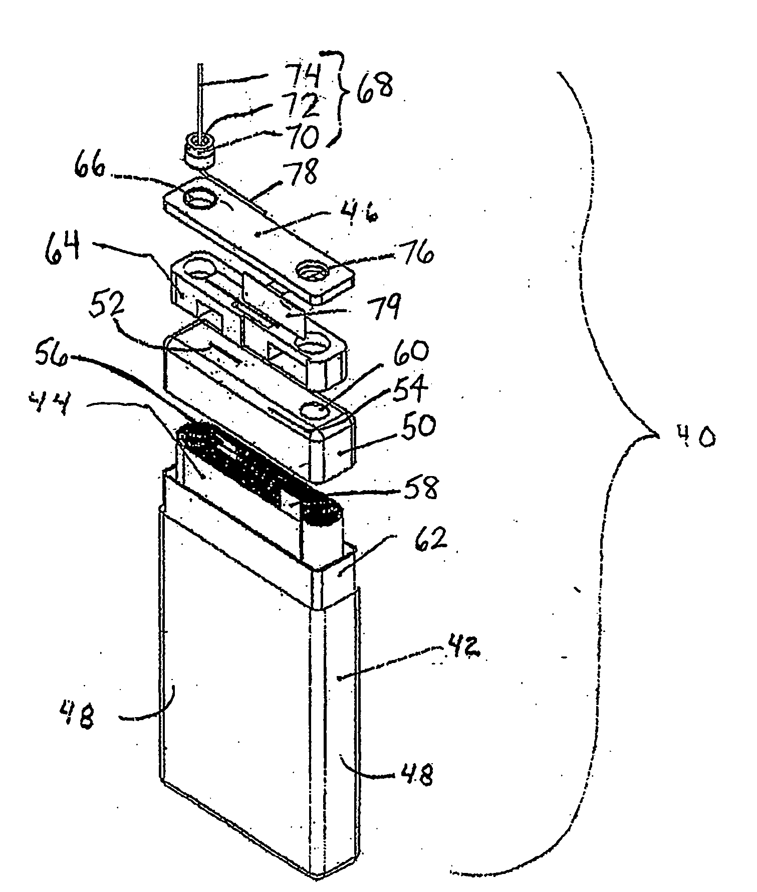
[0013] If such pin and tab are coupled using laser welding, such coupling has been found to provide a joint that is superior than joints formed using other coupling methods (e.g., resistance spot welding). If the coupling method is further provided with the use of a fixture that temporally retains the tab and pin during the coupling process, the method has been found to reduce variability in joint strength properties, (e.g., by improving the repeatability of the process), leading to greater overall yield.

Problems solved by technology

If the coupling method is further provided with the use of a fixture that temporally retains the tab and pin during the coupling process, the method has been found to reduce variability in joint strength properties, (e.g., by improving the repeatability of the process), leading to greater overall yield.

Method used


Image

  • Welding methods and apparatus for batteries
  • Welding methods and apparatus for batteries
  • Welding methods and apparatus for batteries

Examples


Embodiment Construction

[0028] The following discussion is presented to enable a person skilled in the art to make and use the present teachings. Various modifications to the illustrated embodiments will be readily apparent to those skilled in the art, and the generic principles herein may be applied to other embodiments and applications without departing from the present teachings. Thus, the present teachings are not intended to be limited to embodiments shown, but are to be accorded the widest scope consistent with the principles and features disclosed herein. The following detailed description is to be read with reference to the figures, in which like elements in different figures have like reference numerals. The figures, which are not necessarily to scale, depict selected embodiments and are not intended to limit the scope of the present teachings. Skilled artisans will recognize the examples provided herein have many useful alternatives and fall within the scope of the present teachings.

[0029] The p...


PUM

PropertyMeasurementUnit
Angleaaaaaaaaaa

Abstract

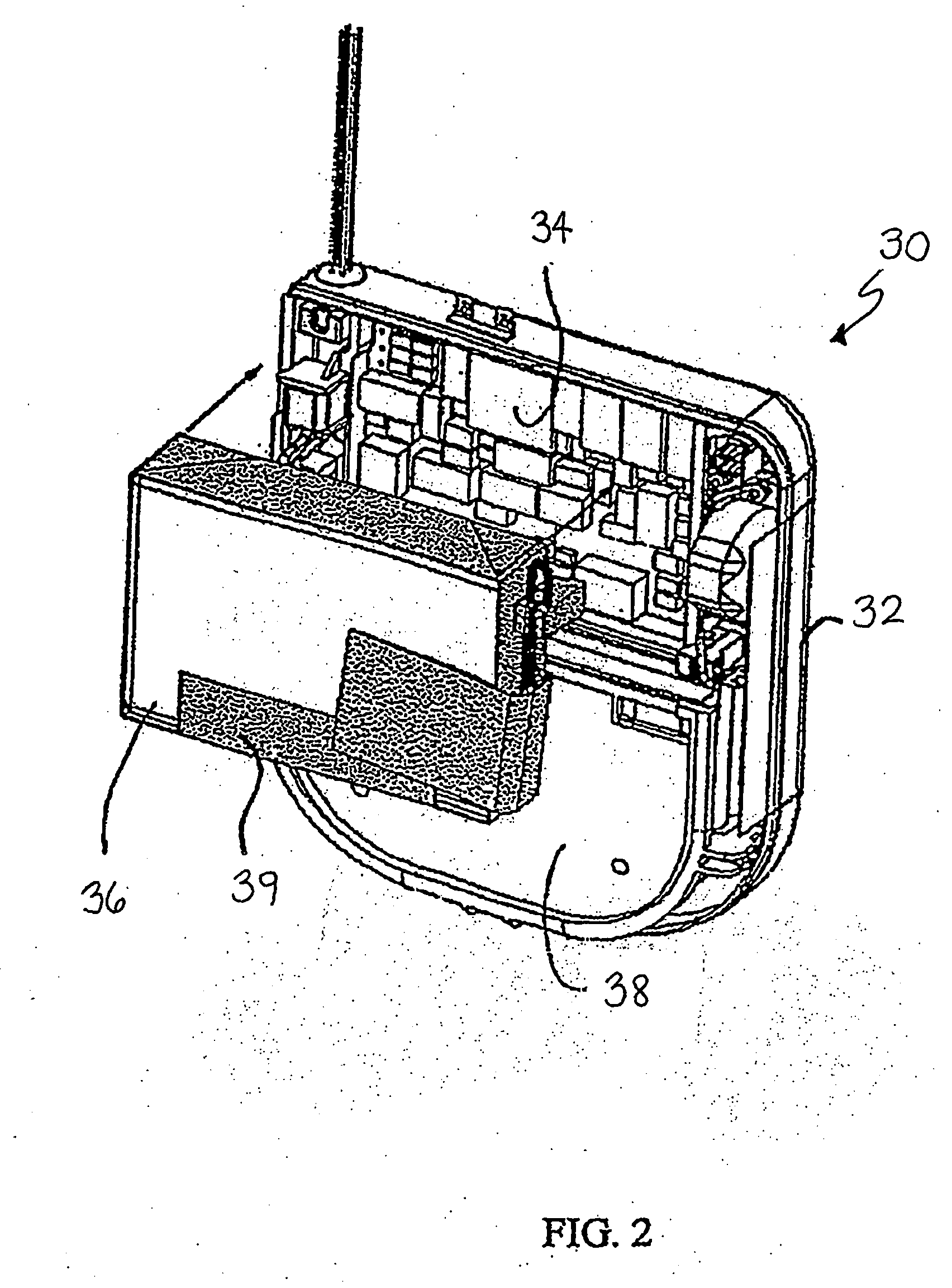
Embodiments of the invention provide an electrochemical cell including an electrode assembly having one or more of the electrodes being coupled to a feedthrough assembly. The one or more electrodes each include a connection tab. The connection tab extends a distance from separation material between the one or more electrodes (e.g., anode and cathode). The connection tab is provided to contact (e.g., electrically connected) a feedthrough pin of the feedthrough assembly by laser welding. The feedthrough pin with respect to the connection tab is oriented in at least one position lying within a 90 degree orientation on the connection tab. The feedthrough pin is coupled to the connection tab by laser welding.

Description

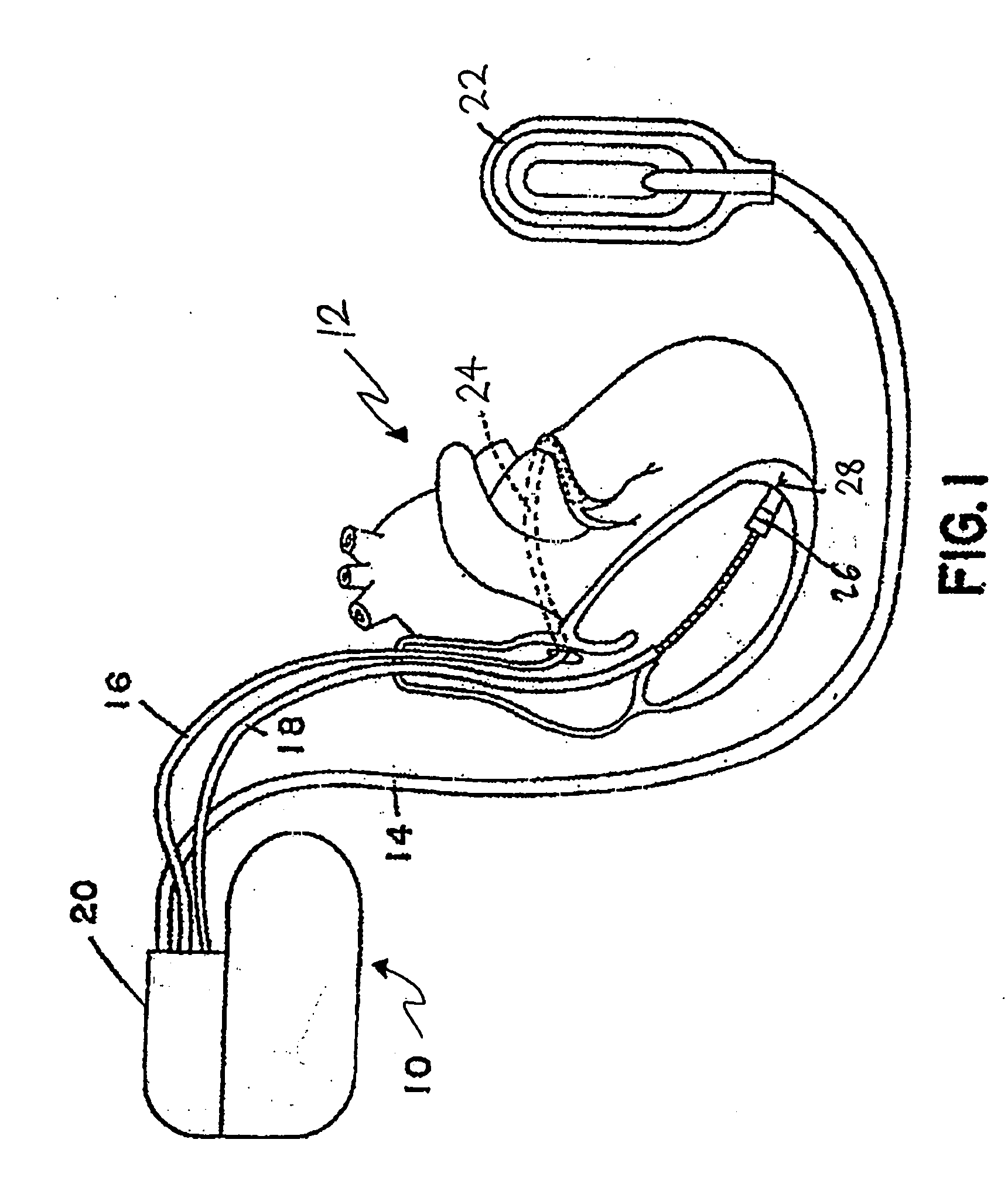
FIELD [0001] The disclosure relates generally to coupling methods, and, more particularly, to a battery incorporating a feedthrough pin and current collector which are coupled using such coupling methods, wherein such battery can be used in implantable medical devices. BACKGROUND SECTION [0002] Implantable medical devices are used to treat patients suffering from a variety of conditions. Examples of implantable medical devices are implantable pacemakers and implantable cardioverter-defibrillators (ICDs), which are electronic medical devices that monitor the electrical activity of the heart and provide electrical stimulation to one or more of the heart chambers, when necessary. For example, pacemakers are designed to sense arrhythmias, i.e., disturbances in heart rhythm, and in turn, provide appropriate electrical stimulation pulses, at a controlled rate, to selected chambers of the heart in order to correct the arrhythmias and restore the proper heart rhythm. The types of arrhythmia...

Claims


Application Information

Patent Timeline
IPC IPC(8): H01M2/06H01M2/08H01M10/04H01M10/052H01M10/0525H01M10/0585H01M10/36H01M50/147H01M50/50
CPCH01M2/0404H01M2/0473H01M2/20H01M10/0404H01M10/0413Y10T29/49114H01M10/0436H01M10/052H01M10/0525H01M10/0585Y02E60/122H01M10/0431Y02E60/10H01M50/147H01M50/15H01M50/50Y02P70/50
Inventor ZHAO, HAILIANGCASBY, KURT J.
Owner MEDTRONIC INC
Learn More