
Integrated circuit with autonomous power management

a technology of integrated circuits and power management, applied in the field of integrated circuits, can solve the problems of limited “visibility” of the operation of individual blocks or cores, high power consumption, and difficult for the integrated circuit designer to anticipate the applications of their chips, and achieve the effect of effective power saving and greater visibility of the operation of cores

Inactive Publication Date: 2006-09-28
DAFCA
View PDF15 Cites 44 Cited by
  • Summary
  • Abstract
  • Description
  • Claims
  • Application Information

AI Technical Summary

Benefits of technology

[0007] The present invention is directed to addressing the above need by way of an autonomous on-chip power management system, which has power management circuitry distributed in an integrated circuit. An integrated circuit generally employs a multi-core or block data processing structure on a semiconductor chip. The term “core” designates pre-packaged design modules that a designer of an integrated circuit employs, usually without any changes. The distributed power management circuitry is able to monitor activities of cores or other functional blocks, providing greater visibility of the operation of cores or functional blocks, and thereby is able to manage power consumption of individual cores or functional blocks locally. The dynamic localized power management can be performed faster than centralized mechanism used in the prior art approaches, thus enabling more real-time applications of power management. The power management system of the present invention is also able to determine an optimal setting in real-time for a particular integrated circuit design to achieve most effective power saving. It achieves this without any change to the operating system of the device, and without any change to the software application it supports. Hence, it is labeled as “autonomous power management system”.
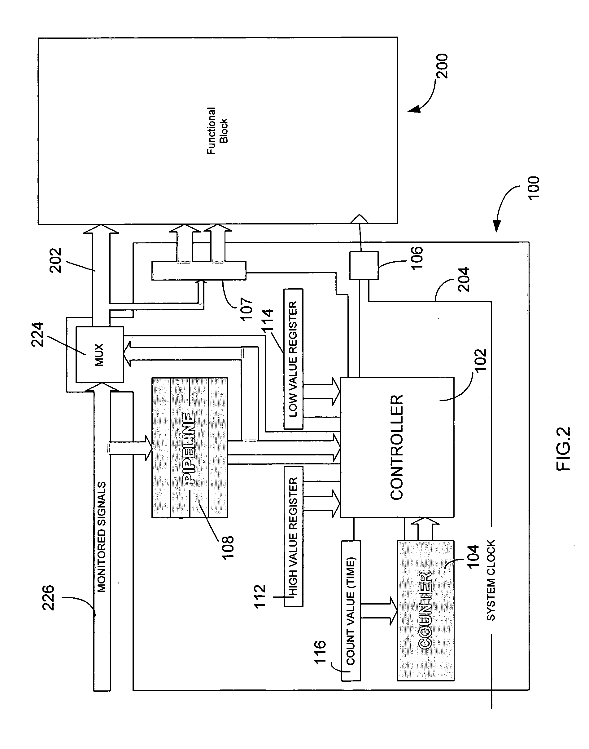
[0009] The power management circuitry may include fixed logic circuits, or alternatively, include at least partially reprogrammable or reconfigurable logic circuits, to observe signals transmitted in the integrated circuit, and based on certain conditions in the observed signals, to set the functional block to a power saving mode. The power management circuitry including at least partially reprogrammable or reconfigurable logic circuits provides the user with the ability of dynamically changing the predetermined conditions under which the functional block should be set to the power saving mode. The reconfigurable circuits also enable the user to fix functional errors in the power management circuitry, as well as functional errors in the integrated circuit, after the integrated circuit has been fabricated.
[0010] Functional blocks generally include sequential logic circuits and / or combinational logic circuits. The power management circuitry, according to one aspect of the present invention, is adapted to reduce the clock speed of a system clock associated with the sequential logic circuits of a functional block, and / or to gate off the inputs to the combinational logic circuits of the functional block, and thereby to reduce power consumption of said functional block.
[0014] According to another aspect of the present invention, the power management circuitry includes a clock control circuit coupled to the controller and a system clock of the functional block. In general, the system clock generates a clock signal to drive the functional block. The clock control circuit is adapted to decrease the speed of the clock signal or disable the clock signal to the functional block in response to instructions from the controller (in other words, the clock rate is lowered or set to be zero), and thereby to set the functional block to a power saving mode.
[0016] In response to the reactivating conditions in the signals at the inputs and / or outputs of the functional block, the power management circuitry should reactivate the functional block by enabling the clock signal and the input signals. One key issue in reactivation of the functional block is that data may be lost during the reactivation because of the delayed response of the power management circuitry and the functional block. The present invention includes several forms to resolve such issues. According to one preferred form of the invention, data loss is avoided by driving the power management circuitry with a clock signal, which has a faster clock speed than the clock signal of the system clock, or alternatively, is a phase-shifted version of the clock signal of the system clock. According to another preferred form, the controller monitors a signal that is associated to the functional block but is remote from the functional block. In these embodiments, the controller is able to detect the reactivating condition in the monitored signals in a relatively early time frame and enables the clock signal and the input signals to the functional block correspondingly earlier, so that the functional block is able to capture the signals at the inputs without losing any data.

Problems solved by technology

High-speed operation of integrated circuits generally leads to high power consumption.
However, as integrated circuits become more complex and more flexible / programmable, it is difficult for the integrated circuit designers to anticipate the applications for their chip and thus to anticipate what signals or variables should be monitored for power management.
Furthermore, while in use, because of the complexity and the large-scale integration of the circuit, the “visibility” of the operation of individual blocks or cores is limited.
Thereby, it becomes difficult for the designers or users to decide when and which sections of the integrated circuit should be disabled or voltage or frequency of which should be scaled for power saving.
These conventional techniques often fail to monitor activity and functionality of individual blocks or cores and thereby fail to manage power consumption at a block or core level.
Therefore, the power saved by these conventional approaches is limited.
One key issue in reactivation of the functional block is that data may be lost during the reactivation because of the delayed response of the power management circuitry and the functional block.

Method used


Image

  • Integrated circuit with autonomous power management
  • Integrated circuit with autonomous power management
  • Integrated circuit with autonomous power management

Examples


Embodiment Construction

[0029] Various embodiments of the present invention will be described with reference to the accompanying drawings. It is to be noted that the same or similar reference numerals are applied to the same or similar parts and elements throughout the drawings, and the description of the same or similar parts and elements will be omitted or simplified.

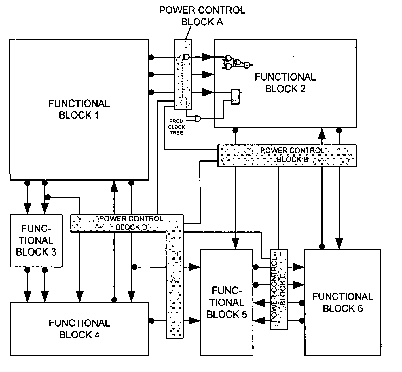
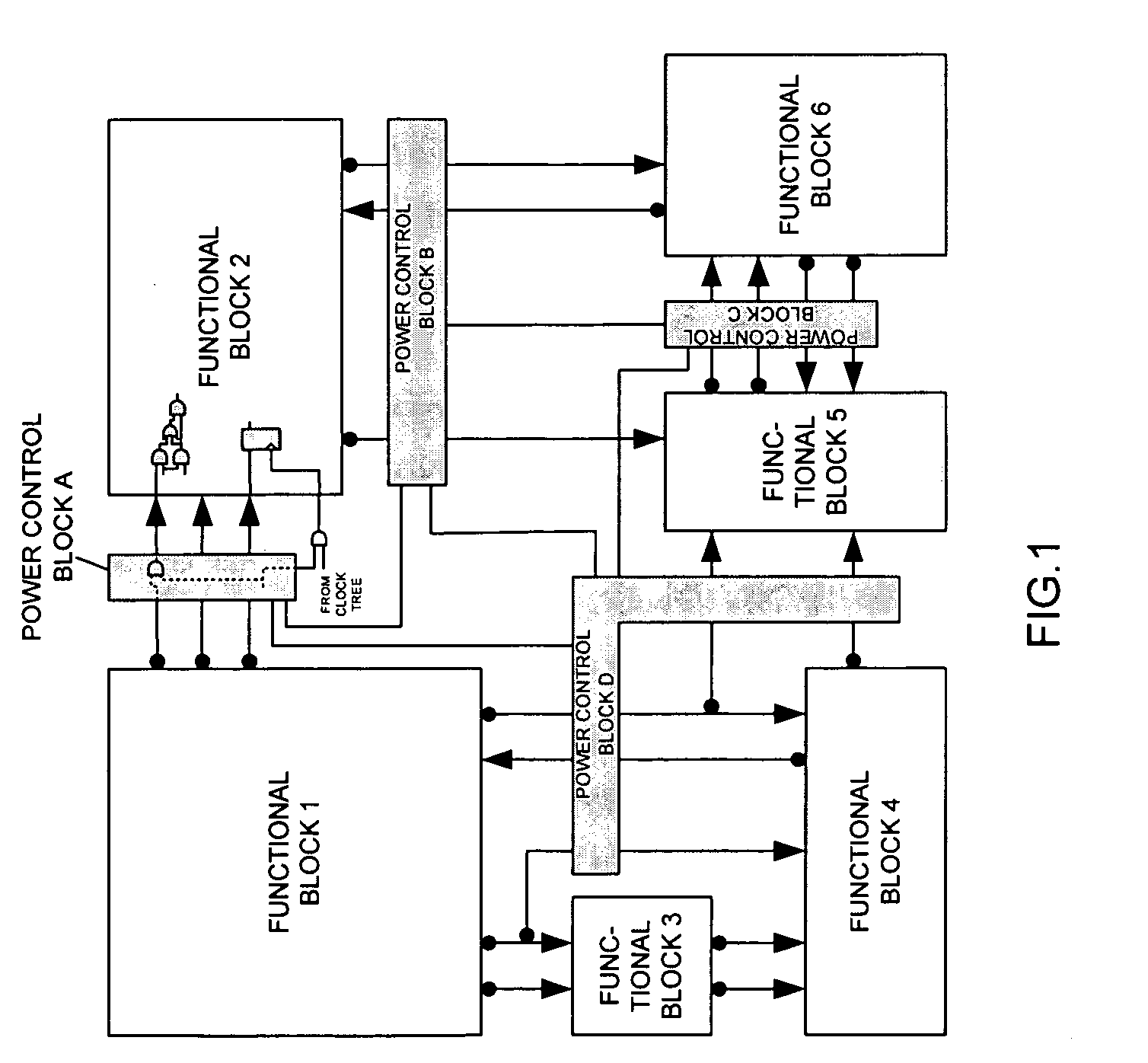
[0030]FIG. 1 illustrates a diagram of an autonomous distributed power management system coupled with multiple functional blocks (functional blocks 1-6 in FIG. 1) in an integrated circuit. The functional block can be a user defined logic block, or a third party's core, or other forms. The autonomous power management system, according to the present invention, includes power management circuitry, which is preferably implemented in the form of circuit blocks distributed among the multiple blocks of the integrated circuit. The circuit blocks indicated as power control blocks A-D in FIG. 1 are connected to interconnects in the integrated circuit...


PUM


Abstract

An autonomous on-chip power management system for managing power consumption of an functional block in an integrated circuit includes power management circuitry configured to monitor signals relevant to the function of the functional block for detecting a predetermined condition associated with the signals, and, in response to the detection of the predetermined condition, to set the functional block to a power saving mode, and, in response to the detection of a predetermined reactivating condition associated with the signals, to set the functional block to a normal operational mode.

Description

FIELD OF THE INVENTION [0001] This invention relates to integrated circuits, and more particularly, to methods and apparatus for autonomously reducing power consumption for integrated circuits. BACKGROUND OF THE INVENTION [0002] High-speed operation of integrated circuits generally leads to high power consumption. One goal in designing an integrated circuit is to reduce power consumption, especially for portable electronic devices. Because the power consumed by an integrated circuit is proportional to the clock frequency and the applied voltage of the integrated circuit, the conventional approaches for reducing power consumption have focused on clock and voltage scaling. These conventional approaches include a) reducing the operating voltage of the integrated circuit, b) reducing the clock frequency of the integrated circuit, and c) shutting off the clock to the integrated circuit. [0003] In these conventional approaches, various algorithms are used to determine when to initiate pow...

Claims


Application Information

Patent Timeline
IPC IPC(8): G06F1/00
CPCG06F1/3203
Inventor ABRAMOVICI, MIRONBRADLEY, PAUL A.LEVIN, PETER L.MEMMI, GERARD
Owner DAFCA
Learn More