
Mixer, High-Frequency transmitting/receiving apparatus having the same, radarapparatus having the high-frequency transmitting/receiving apparatus, and vehicle equipped with radar apparatus

a high-frequency transmitting/receiving apparatus and mixer technology, applied in the field of mixers, can solve the problems of poor controllability, impractical scale-up of the adjustment mechanism as a whole, and the risk of electrical length variation

Inactive Publication Date: 2006-09-28
KYOCERA CORP
View PDF8 Cites 19 Cited by
  • Summary
  • Abstract
  • Description
  • Claims
  • Application Information

AI Technical Summary

Benefits of technology

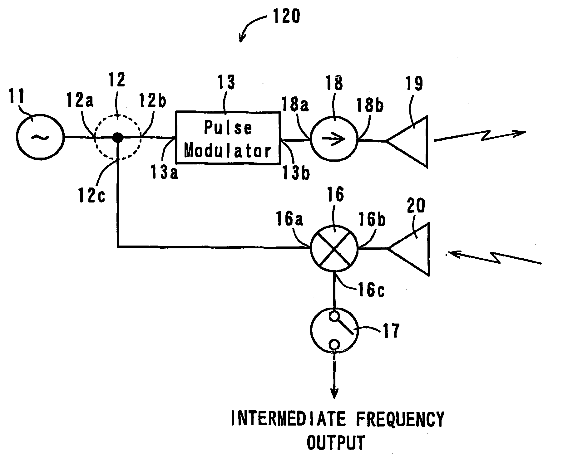
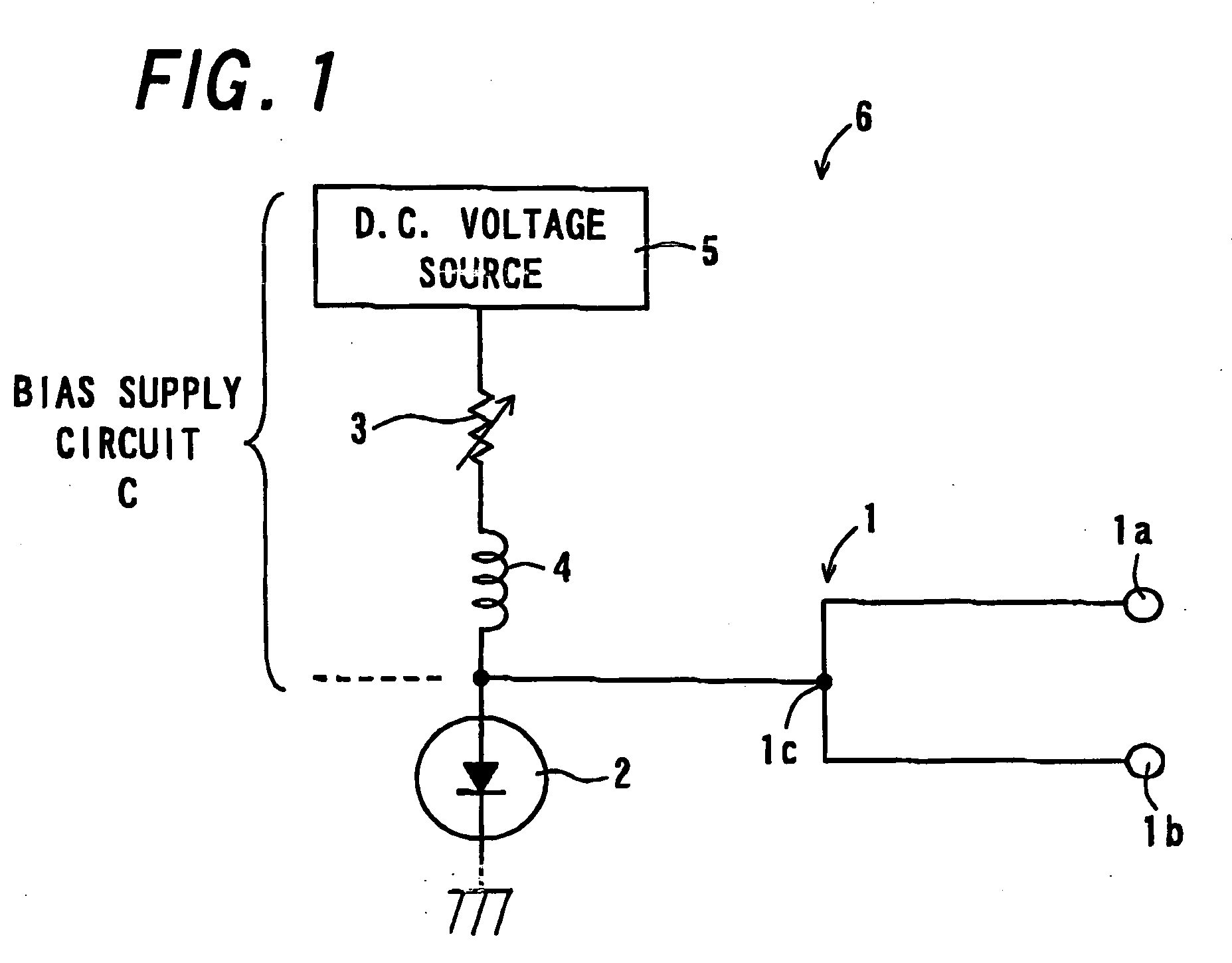
[0018] The invention has been devised in view of the above-described problems of which improvement is desired with the conventional art, and accordingly one object of the invention is to provide a mixer in which a bias supply circuit of a high-frequency detection element for constituting the mixer is provided with a pre-set variable resistor thereby to keep characteristics such as mixing characteristics and transmission characteristics of the mixer tuned satisfactorily, and also provide a high-frequency transmitting / receiving apparatus having the mixer that is remarkable for constructional simplicity and performance, and is capable of offering excellent reception performance, with high transmission power ON / OFF ratio, by preventing part of a high-frequency signal intended for transmission from being transmitted as an unwanted signal when a modulator is kept in an OFF state.

Problems solved by technology

However, conventional constructions have the following disadvantages.
In this case, however, there is a risk of the electrical length being varied in the presence of only slight play in the structure.
This gives rise to a problem of poor controllability.
In an attempt to overcome the problem, removing the play nearly perfectly leads to an impractical scale-up of the adjustment mechanism as a whole.
Furthermore, occurrence of oscillation or thermal expansion and contraction causes deviation in the electrical length of the adjustment mechanism such as the cavity resonator and the movable part.
This gives rise to a problem of poor stability.
In addition, in the conventional high-frequency transmitting / receiving apparatus having such a mixer, because of tuning inaccuracy or instability in the mixer, it is impossible to ensure a uniform reception sensitivity.
This gives rise to a problem of difficulty in attaining excellent characteristics with stability.
This leads to degradation of the transmission / reception performance.
This gives rise to a problem that part of the high-frequency signal RF is unlikely to be received properly.
This leads to narrowness in detectable range and susceptibility to erroneous detection, which give rise to a problem of a delay in detecting an object to be detected.
However, because of the delay of target detection, an abrupt action is caused in the vehicle or small boat after the detection operation.

Method used


Image

  • Mixer, High-Frequency transmitting/receiving apparatus having the same, radarapparatus having the high-frequency transmitting/receiving apparatus, and vehicle equipped with radar apparatus
  • Mixer, High-Frequency transmitting/receiving apparatus having the same, radarapparatus having the high-frequency transmitting/receiving apparatus, and vehicle equipped with radar apparatus
  • Mixer, High-Frequency transmitting/receiving apparatus having the same, radarapparatus having the high-frequency transmitting/receiving apparatus, and vehicle equipped with radar apparatus

Examples


implementation example

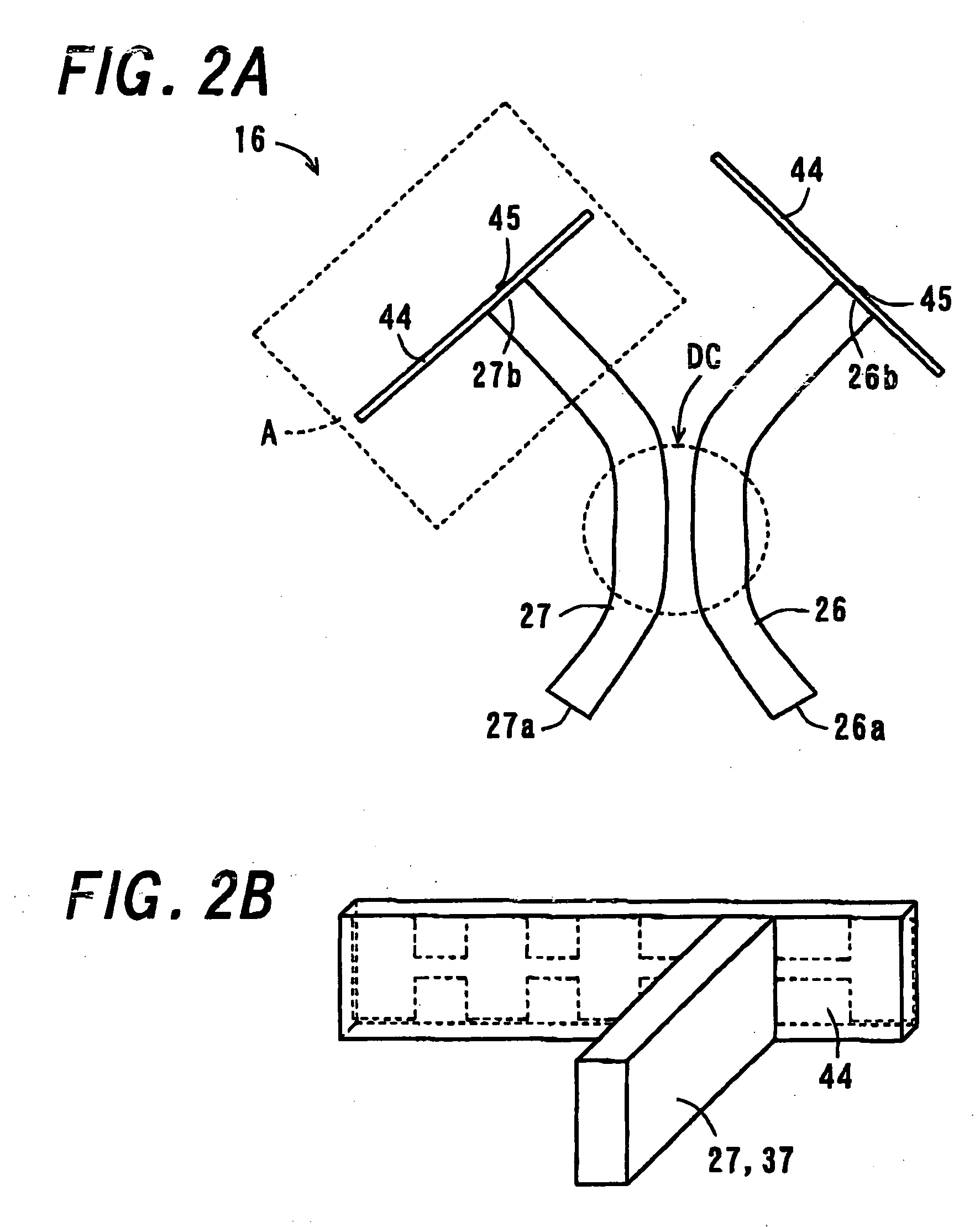
[0183] As an actual implementation example, the high-frequency transmitting / receiving apparatus 110 of the invention as shown in FIGS. 6 and 7 was constructed as follows. As a pair of parallel plate conductors 21 (one of them is not illustrated in the figures), two pieces of 6 mm-thick Al (aluminum) plates were arranged at an interval of 1.8 mm so as to have surfaces thereof in a thickness direction confronted each other. Between the Al plates were interposed the first to fifth dielectric strip lines 22, 23, and 25 to 27 made of cordierite ceramics having a relative dielectric constant of 4.8. Each of the dielectric strip lines has a sectional profile of 1.8 mm in height and 0.8 mm in width in one virtual plane perpendicular to an extending direction of the lines. As the circulator 14, two pieces of ferrite plates 24 each having a diameter of 2 mm and a thickness of 0.23 mm were prepared for use. One of them was brought into intimate contact with one parallel plate conductor 21 (the...


PUM


Abstract

A mixer capable of keeping mixing characteristics tuned satisfactorily is provided. A coupler includes two input ends, and one or two output ends. At the output end is disposed a Schottky-barrier diode acting as a high-frequency detection element. Connected to the Schottky-barrier diode is a bias supply circuit having a trimmable chip resistor acting as a pre-set variable resistor, for controlling a bias current which passes through the Schottky-barrier diode. By adjusting the resistance of the trimmable chip resistor, it is possible to control a bias current passing through the Schottky-barrier diode, and thereby keep mixing characteristics tuned satisfactorily.

Description

BACKGROUND OF THE INVENTION [0001] 1. Field of the Invention [0002] The present invention relates to a mixer for use in a millimeter-wave integrated circuit, a millimeter-wave radar module, or the like, and more particularly to a mixer in which a bias supply circuit of a high-frequency detection element as a component of the mixer is provided with a pre-set variable resistor thereby to keep characteristics such as mixing characteristics and transmission characteristics of the mixer tuned satisfactorily, and to a high-frequency transmitting / receiving apparatus having the mixer. [0003] The present invention also relates to a radar apparatus having the high-frequency transmitting / receiving apparatus, and a vehicle equipped with the radar apparatus. [0004] 2. Description of the Related Art [0005] Some examples of mixers of conventional design have hitherto been known, such as those which have been disclosed in Japanese Unexamined Patent Publications JP-A 10-242766 (1998), JP-A2001-20353...

Claims


Application Information

Patent Timeline
Patent Type & Authority Applications(United States)
IPC IPC(8): G01S13/08G01S13/93
CPCG01S7/03G01S7/28H03D9/0633
Inventor TAKENOSHITA, TAKESHIHAYATA, KAZUKIKISHIDA, YUJI
Owner KYOCERA CORP
Learn More