Switching power supply circuit

ircuit technology, applied in the field of switching power supply circuits, can solve the problems of significant decrease of power conversion efficiency, difficulty in obtaining the saturation state, and breakdown voltage associated with putting voltage resonant converters into practical use, so as to improve the performance of parts elements, reduce cost, and enhance the reliability of a power supply circuit

Inactive Publication Date: 2006-09-21
SONY CORP
View PDF7 Cites 15 Cited by
  • Summary
  • Abstract
  • Description
  • Claims
  • Application Information

AI Technical Summary

Benefits of technology

[0066] Moreover, since the peak level of a resonant voltage pulse is suppressed by an active clamp circuit, low-breakdown-voltage products can be selected as parts elements typified by a main switching element. Thus, the performance of the parts elements can be improved, which allows enhancement of reliability of a power supply circuit, a cost decrease, and reduction of size and weight of the circuit.

Problems solved by technology

However, since characteristics of high-breakdown-voltage switching elements are currently being improved for example, problems about breakdown voltage associated with putting voltage resonant converters into practical use are being cleared up.
When the coupling coefficient k has such a value, the coupling degree between the primary and secondary sides may be regarded as loose coupling, and thus it is difficult to obtain the saturation state.
Even if an IC is developed so that an IC can drive switching elements with such a high frequency, the driving of switching elements with a high frequency leads to a significant decrease of the power conversion efficiency.
It therefore is substantially impossible to put this IC into practical use for a power supply circuit.
As described above, it is very difficult to achieve a wide-range compatible power supply circuit by use of the configuration shown in FIG. 9 for example.

Method used


Image

  • Switching power supply circuit
  • Switching power supply circuit
  • Switching power supply circuit

Examples


first embodiment

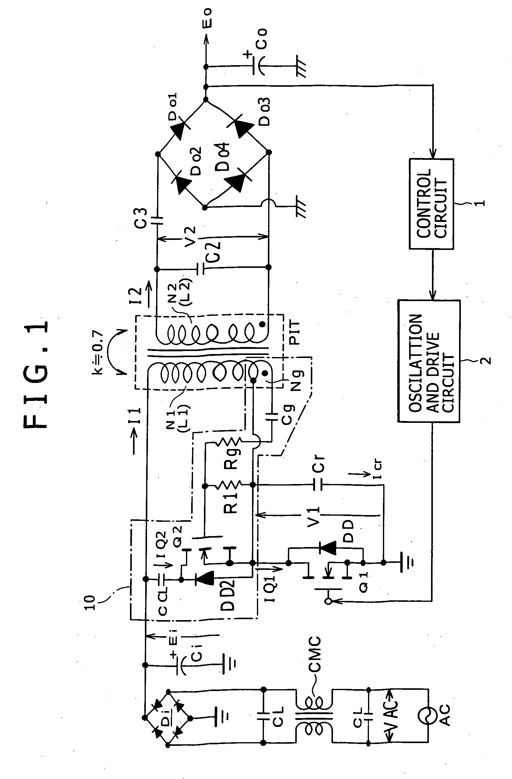
[0079]FIG. 1 is a circuit diagram illustrating a configuration example of a power supply circuit according to the present invention, as one of best modes (embodiments) for carrying out the invention. The power supply circuit in FIG. 1 includes, as its basic configuration, a single-ended voltage resonant switching converter.

[0080] In the switching power supply circuit in FIG. 1, the lines from a commercial alternating-current power supply AC are provided with a pair of common mode choke coils CMC and two across-line capacitors CL. These common mode choke coils CMC and the across-line capacitors CL form a noise filter that removes common mode noises included in the lines from the commercial alternating-current power supply AC.

[0081] A voltage from the commercial alternating-current power supply AC (an AC input voltage VAC) is rectified by a bridge rectifier circuit Di, and the rectified output is charged in the smoothing capacitor Ci. Thus, a rectified and smoothed voltage Ei is obta...

second embodiment

[0241]FIG. 7 illustrates the configuration of a power supply circuit according to the invention.

[0242] Note that FIG. 7 shows only the configuration of the secondary side from the isolation converter transformer PIT. Since parts other than these illustrated parts are the same as those of FIG. 1, the illustration thereof is omitted in FIG. 7. The same parts in FIG. 7 as those in FIG. 1 are given the same numerals and will not be described in detail below. This respect also applies to FIG. 8 similarly.

[0243] In the power supply circuit in FIG. 7, the secondary-side parallel resonant capacitor C2 is connected in parallel to the whole secondary winding N2. Thus, the leakage inductance L2 of the secondary winding N2 (N2A+N2B) and the capacitance of the secondary-side parallel resonant capacitor C2 form a secondary-side parallel resonant circuit. In addition, a secondary-side series resonant circuit is formed in the secondary-side rectifier circuit as described above.

[0244] The second e...

third embodiment

[0255]FIG. 8 illustrates a configuration example of a power supply circuit according to the invention.

[0256] In the power supply circuit of FIG. 8, one secondary-side parallel resonant capacitor C2 and one secondary-side series resonant capacitor C3 are coupled to the secondary winding N2 with the same connecting structure as that of FIG. 1. Thus, on the secondary side from the isolation converter transformer PIT, a secondary-side parallel resonant circuit is formed of the leakage inductance L2 of the secondary winding N2 and the capacitance of the secondary-side parallel resonant capacitor C2, and a secondary-side series resonant circuit is formed of the leakage inductance L2 of the secondary winding N2 and the capacitance of the secondary-side series resonant capacitor C3. In addition, a voltage-doubler half-wave rectifier circuit is provided as a secondary-side rectifier circuit.

[0257] This voltage-doubler half-wave rectifier circuit is formed by coupling two rectifier diodes Do...


PUM


Abstract

A wide-range compatible voltage resonant converter provides high efficiency and allows use of low-breakdown-voltage products for a circuit. The voltage resonant converter is provided with a secondary-side parallel resonant circuit and a secondary-side series resonant circuit, and a loose coupling state is established in which the coupling coefficient of an isolation converter transformer is about 0.7 or less. Thus, a constant-voltage control characteristic is obtained as a sharp unimodal characteristic, which narrows the switching frequency control region required for stabilization of an output voltage. In addition, a primary-side parallel resonant frequency, a secondary-side parallel resonant frequency and a secondary-side series resonant frequency are set so that a favorable power conversion efficiency is obtained. Moreover, an active clamp circuit is provided to suppress the peak level of a resonant voltage pulse to thereby allow use of low-breakdown-voltage products for a switching element and so on.

Description

CROSS-REFERENCE TO RELATED APPLICATIONS [0001] The present application claims priority from Japanese Patent Application No. JP 2005-064482 filed on Mar. 8, 2005, the disclosure of which is hereby incorporated by reference herein. BACKGROUND OF THE INVENTION [0002] The present invention relates to a switching power supply circuit including a voltage resonant converter. [0003] As types of a so-called soft switching power supply that employs a resonant converter, a current resonant type and a voltage resonant type have been widely known. Currently, half-bridge connected current resonant converters formed of a two-transistor switching element have been widely employed since they can easily be put into practical use. [0004] However, since characteristics of high-breakdown-voltage switching elements are currently being improved for example, problems about breakdown voltage associated with putting voltage resonant converters into practical use are being cleared up. Furthermore, it is known...

Claims


Application Information

Patent Timeline
Patent Type & Authority Applications(United States)
IPC IPC(8): H02M3/335
CPCH02M3/3385Y02B70/1433H02M2001/0058Y02B70/1491Y02B70/10Y02P80/10H02M1/0058H04N21/2223H04N5/907H04N5/77H04N7/181G03B17/08G09B5/02
Inventor YASUMURA, MASAYUKI
Owner SONY CORP
Why Eureka
Try Eureka