
Heat-dissipating structure for flat panel display

a flat panel display and heat dissipation structure technology, applied in the direction of electrical apparatus casings/cabinets/drawers, cooling/ventilation/heating modifications, instruments, etc., can solve the problems of heat dissipation efficiency, heat from electric units, and heat from flat panel displays

Inactive Publication Date: 2006-09-14
CORETRONIC
View PDF20 Cites 13 Cited by
  • Summary
  • Abstract
  • Description
  • Claims
  • Application Information

AI Technical Summary

Benefits of technology

[0007] An objective of the present invention is to provide a heat-dissipating structure for a flat panel display with a good heat-dissipating efficiency.
[0012] Accordingly, by utilizing the present heat-dissipating structure for the flat panel display, which comprises above mentioned elements such as the heat-collector plate, the soft thermal-pad and the heat-sink component, the heat generated from the electric units of the flat panel display is able to be conducted well.

Problems solved by technology

Accordingly, a heat-dissipating efficiency becomes an important issue to the flat panel display.
The heat-dissipating efficiency is therefore limited, especially in the condition that the heat is only dissipated by air convection.
These usually leads to over heat from the electric units and reduce product life time of the flat panel display 2.

Method used


Image

  • Heat-dissipating structure for flat panel display
  • Heat-dissipating structure for flat panel display
  • Heat-dissipating structure for flat panel display

Examples


Embodiment Construction

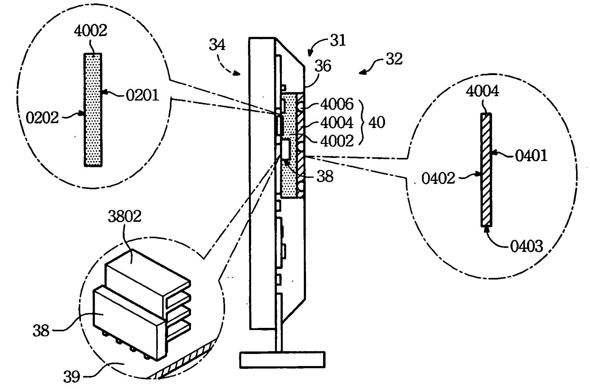
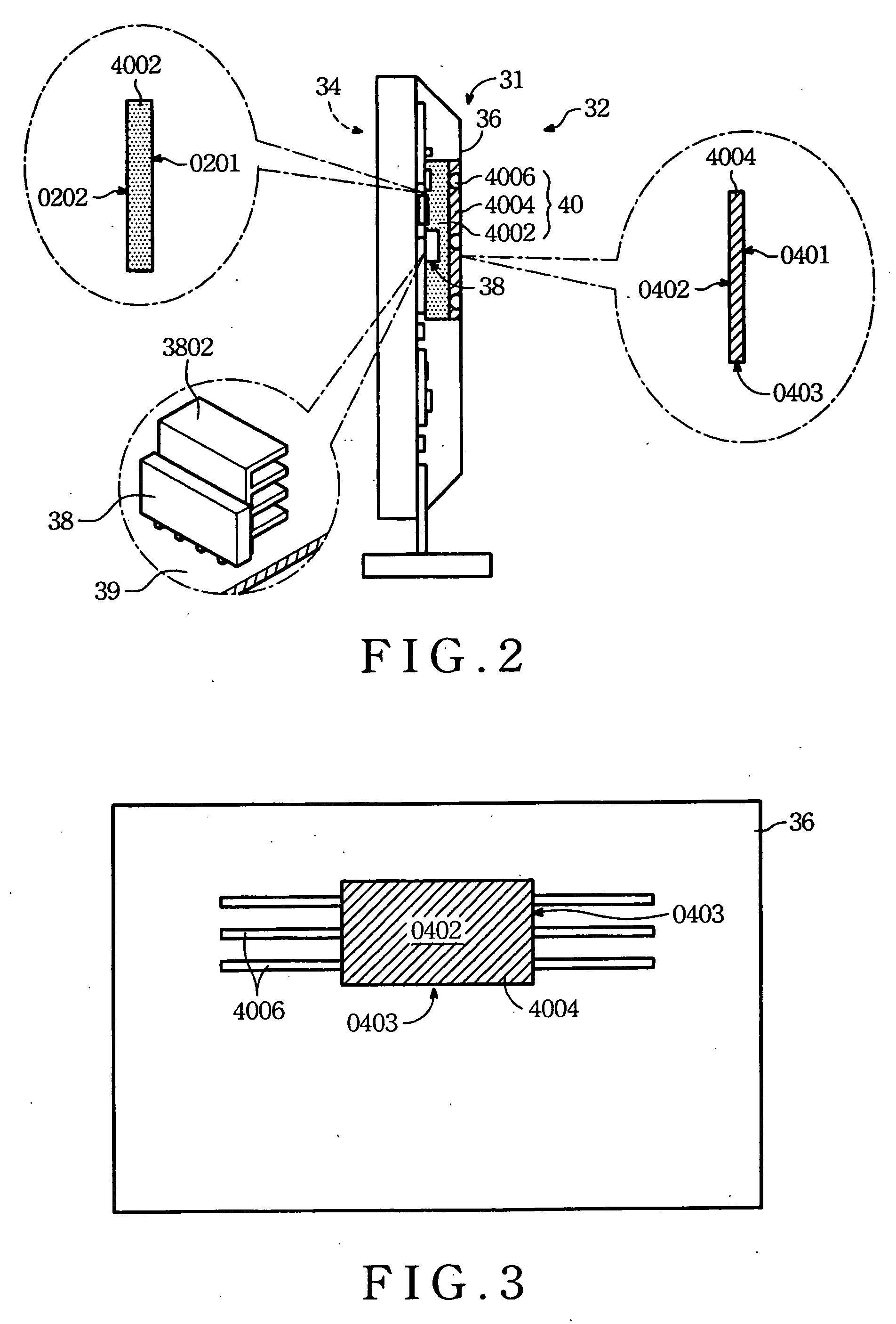
[0018] Please refer to FIG. 2 and FIG. 3. FIG. 2 shows a cross section view of a flat panel display 32 according to the present invention. FIG. 3 shows a rear view of a heat-dissipating structure 31 of the flat panel display 32. The heat-dissipating structure 31 of the present invention comprises a heat-collector plate 4004, a soft thermal-pad 4002 and at least one heat-sink component 4006. The flat panel display 32 comprises a display screen 34, a back bezel 36 and many other electric units 38 enclosed by a front frame of the display screen 34 and the back bezel 36. The electric units 38 generate heat while they are operated. A power supply element, which is one of the electric units 38, generates heat of a particularly high heat power. Generally, a heat-sink structure 3802 is disposed on the electric unit 38 for enhancing heat sink efficiency.

[0019] The heat-collector plate 4004 has a first-face 0401, a second-face 0402 and a plurality of edge-sides 0403. The first-face 0401 is c...


PUM


Abstract

A heat-dissipating structure for a flat panel display comprises a heat-collector plate, a soft thermal-pad and at least one heat-sink component. The heat-collector plate is made of metal material having a first-face, a second-face and a plurality of edge-sides. The first-face is contact with a back-bezel of the flat panel display. The soft thermal-pad is made of soft material with high thermal conductivity. The soft thermal-pad has a bottom-face and a top-face. The bottom-face is contact with the second-face. The top-face is contact with a heat-sink structure of an electric unit of the flat panel display. The heat-sink component is connected with at least one of the edge-side of the heat-collector plate. The heat-sink component is capable of conducting heat and expanding heat sink area.

Description

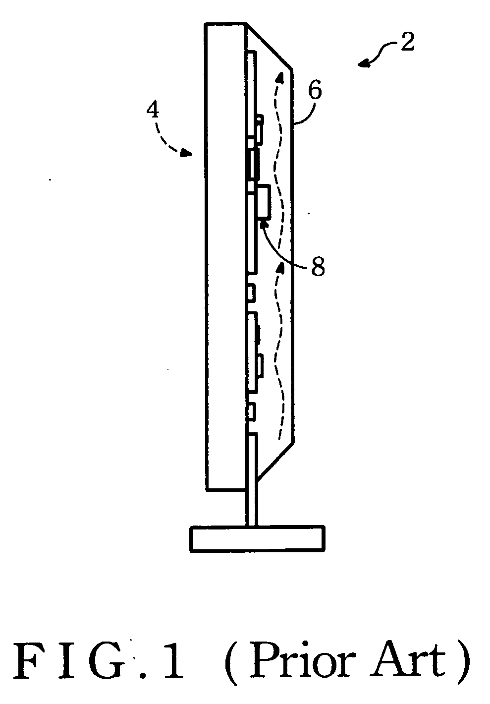
BACKGROUND OF THE INVENTION [0001] (1) Field of the Invention [0002] The present invention generally relates to a heat-dissipating structure and particularly relates to a heat-dissipating structure for a flat panel display. [0003] (2) Description of the Prior Art [0004] A flat panel display, such as a Plasma Display Panel (PDP) and a LCD (Liquid Crystal Display) monitor, generally has a thin shape. Accordingly, a heat-dissipating efficiency becomes an important issue to the flat panel display. [0005] Please refer to FIG. 1. A conventional flat panel display 2 comprises a display screen 4, a back bezel 6 and many other electric units enclosed by a front frame of the display screen 4 and the back bezel 6. The electric units generate heat while they are operated. A power supply element 8, which is one of the electric units, generates heat of a particularly high heat power. A conventional solution is to dissipate heat by air convection through a gap between the power supply element 8 an...

Claims


Application Information

Patent Timeline
IPC IPC(8): G06F1/20
CPCG02F1/133382
Inventor HSU, SHENG-HSIANGCHOU, BOR-BIN
Owner CORETRONIC
Learn More