
Four panel projection system

a projection system and panel technology, applied in the field of four panel projection system, can solve the problems of reducing the brightness of uhp lamps, sacrificing color balance, and wasting color resources, so as to increase the color gamut, increase the transmission throughput, and increase the color brightness

Inactive Publication Date: 2006-09-07
REAID INC
View PDF58 Cites 21 Cited by
  • Summary
  • Abstract
  • Description
  • Claims
  • Application Information

AI Technical Summary

Benefits of technology

[0009] Disclosed herein is a four panel architecture that provides a four-primary color based projection system. For instance, four primary color components that may be used with this system include red, yellow, green, and blue. Including yellow light as a fourth primary has several advantages that address the deficiencies of three-panel systems discussed above. First, color brightness is increased due to an increased transmitted throughput using the otherwise-discarded yellow light from a UHP light source. Second, color gamut is increased because the availability of four primary color components allows a chromatic reproduction not available to conventional three-primary color based systems. In particular, the primary green color can be a much richer green.

Problems solved by technology

However, a drawback of such conventional three-color display systems is that they are inherently limited to the triangular color gamut defined by saturated RGB primaries, which in the case of video projection systems, force the bright yellow emission of UHP lamps to be discarded.
Another drawback of such systems is that color balance is often sacrificed to improve brightness of the projected image.
However, because image brightness is already a problem in conventional display systems, it is often undesirable to further decrease brightness in order to achieve a more desirable color temperature.

Method used


Image

  • Four panel projection system
  • Four panel projection system
  • Four panel projection system

Examples


Embodiment Construction

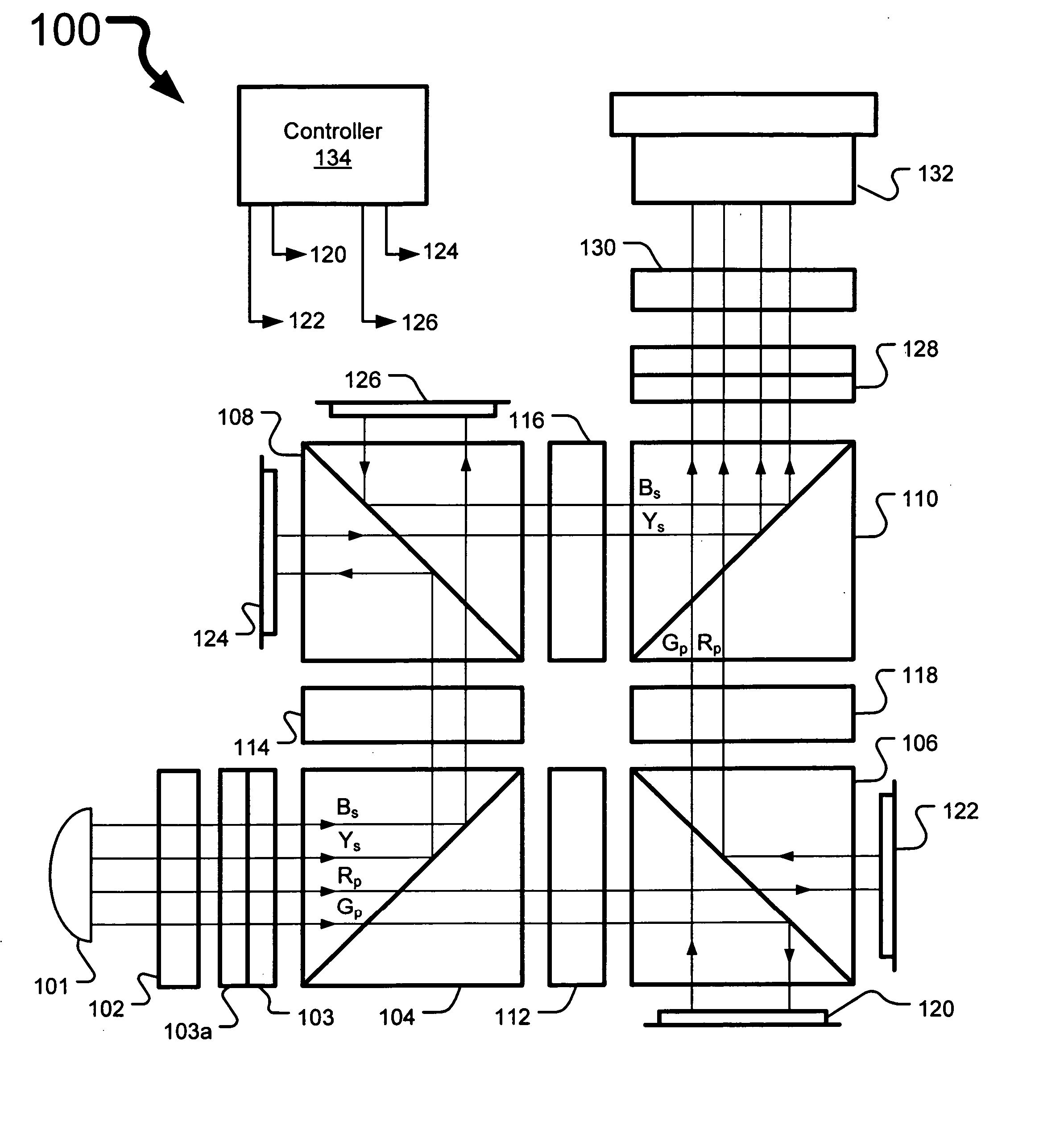
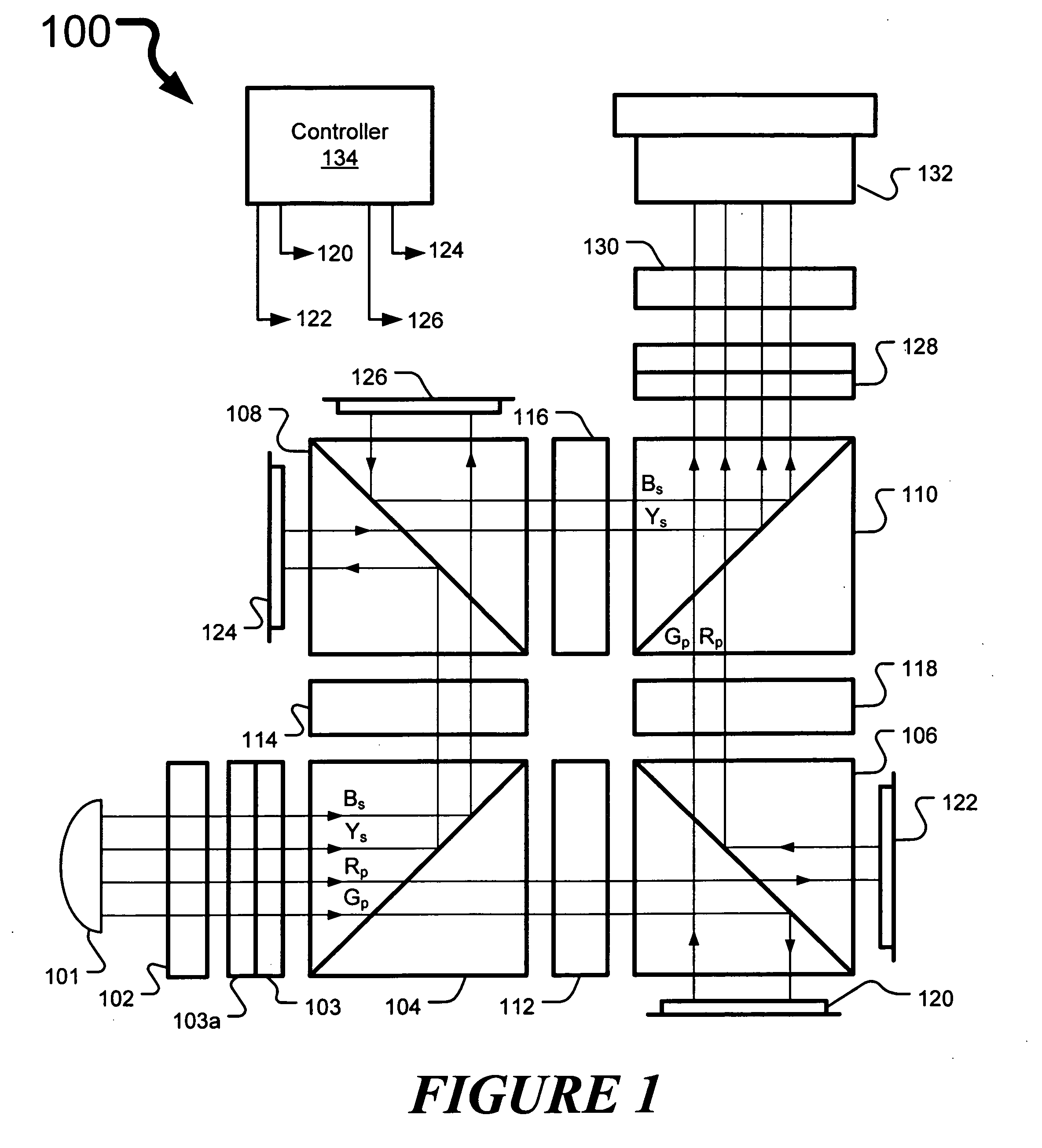
[0018]FIG. 1 is a diagram that illustrates an embodiment of a four panel projection system 100. The four panel projection system 100 includes a light source 101, a pre-polarizer 102, wavelength-selective polarization filters 103, 103a, 112-118, an input beam splitter 104, polarizing beam splitters (PBS) 106-110, LCOS reflective panels 120-126, projection lens 132, and controller 134, arranged as shown. The four panel projection system 100 may also include exit wavelength-selective polarization filters 128a, 128, and / or polarization filter 130.

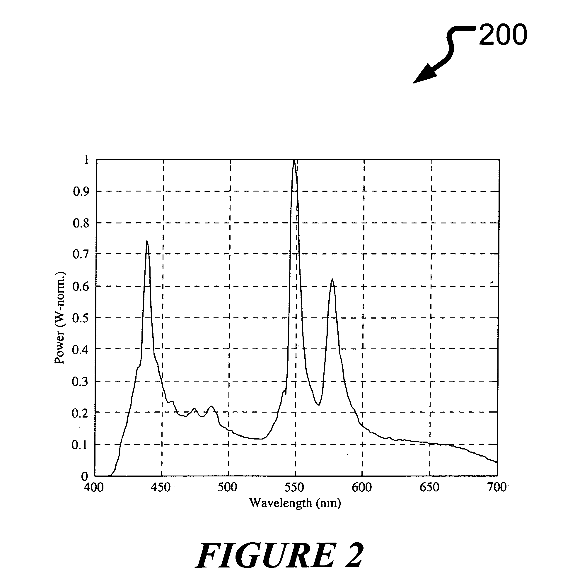
[0019] Light source 101 may be a standard UHP mercury illumination source, metal-halide source, a light emitting diode-based light source, a laser-based light source, a xenon light source, or any other light source that generates visible spectra with a plurality of color components. Controller 134 may provide control signals to panels 120-126 to modulate the respective color components with color component image information. Controller 134 may...


PUM


Abstract

A four-panel liquid-crystal-on-silicon (LCOS) projection display system utilizes four available ports of a beam splitter and polarization filter architecture to provide a four-color component image with an increased brightness and color gamut compared with typical three-color component images. The projection display system includes a light source, four light modulating panels, a light directing subsystem, and a projection lens. The light source is operable to generate light having four color components. Each of the four light modulators is operable to generate a respective image associated with the respective one of the four color components. The light directing subsystem is operable to split the four color components before modulation and recombine them after modulation, and each light modulator is located at a separate port of the light directing subsystem. The projection lens is operable to project an image of the modulated combined color components.

Description

CROSS REFERENCE TO RELATED APPLICATIONS [0001] This Application claims the benefit of U.S. Provisional Application Ser. No. 60 / 658,455, filed on Mar. 4, 2005, and entitled “Four Panel Architecure,” which is commonly assigned with the present application and incorporated herein by reference.BACKGROUND [0002] 1. Technical Field [0003] The present disclosure relates to a four panel projection system used in a projection type display. [0004] 2. Description of Related Art [0005] It is generally desirable for projection systems to produce high quality images while being compact and inexpensive. Conventional three-color display systems are known that provide projection of red, green, and blue color components. However, a drawback of such conventional three-color display systems is that they are inherently limited to the triangular color gamut defined by saturated RGB primaries, which in the case of video projection systems, force the bright yellow emission of UHP lamps to be discarded. [00...

Claims


Application Information

Patent Timeline
IPC IPC(8): G03B21/14
CPCG02B27/1026G02B27/145G02F1/133621G03B21/14G03B21/20G03B33/04H04N9/3105H04N9/3197G03B21/005G03B21/2073
Inventor ROBINSON, MICHAEL G.
Owner REAID INC
Learn More