Variator disk and variator for a toroidal transmission
- Summary
- Abstract
- Description
- Claims
- Application Information
AI Technical Summary
Benefits of technology
Problems solved by technology
Method used
Image
Examples
Embodiment Construction
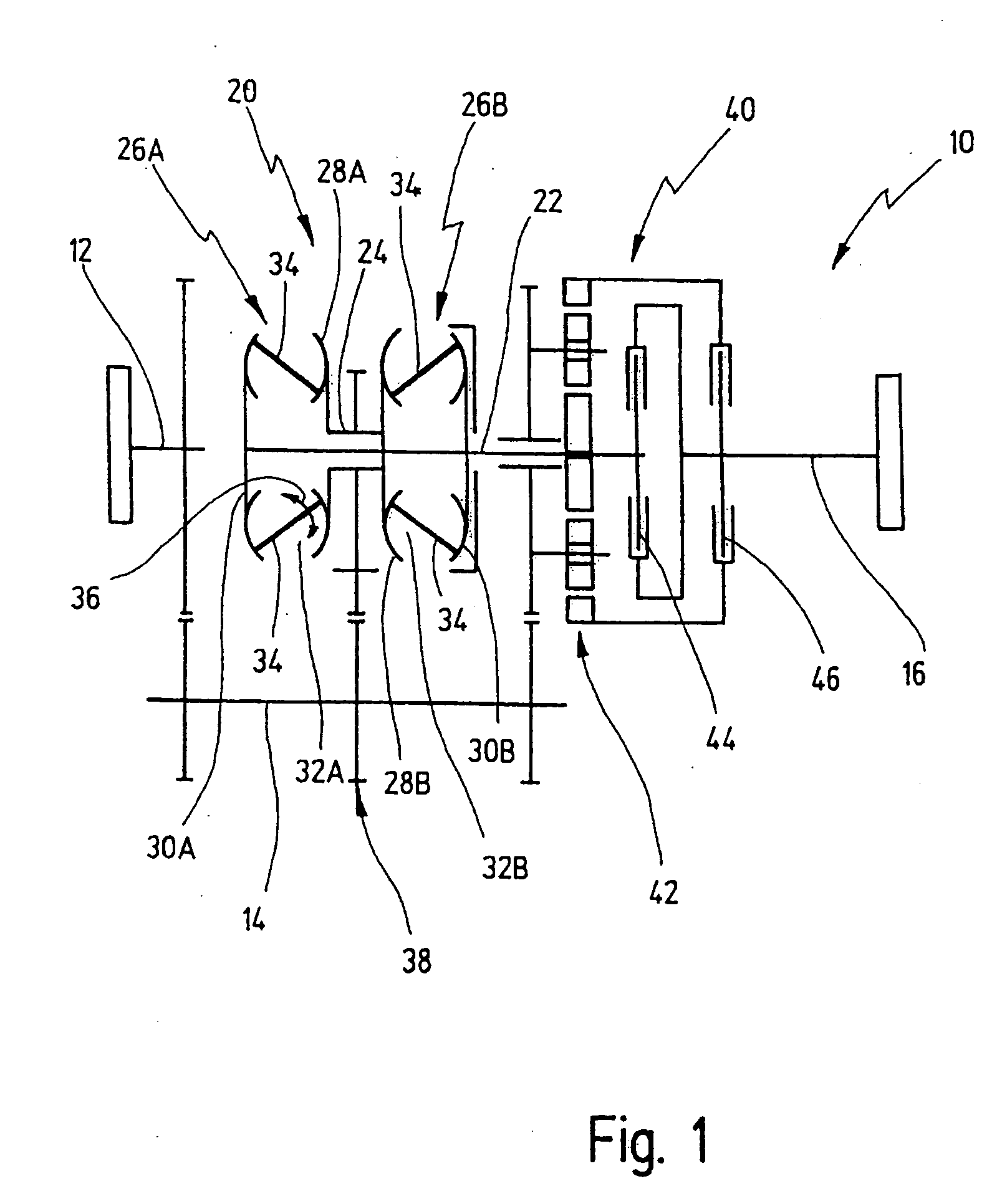
[0064] In FIG. 1, a diagrammatically illustrated toroidal transmission is generally designated by 10.
[0065] The toroidal transmission 10 has a transmission input shaft 12, a countershaft 14 and a transmission output shaft 16.
[0066] A variator arrangement in the toroidal transmission 10 is shown at 20. The variator arrangement 20 has a variator main shaft 22 and a variator secondary shaft 24. Furthermore the variator arrangement 20 contains two variators 26A, 26B.
[0067] Each variator has a driving disk 28A, 28B and a driven disk 30A, 30B.
[0068] The driving disks 28A, 28B enclose, together with the respective driven disks 30A, 30B, in each case a toroidal space 32A, 32B.
[0069] A plurality of rollers 34, as a rule in each case three rollers 34, are arranged in the toroidal spaces 32A, 32B in each case so as to be distributed circumferentially over the toroidal space.
[0070] The rollers 34 can be adjusted spatially within the toroidal space 32 by means of an actuator mechanism, not...
PUM
 Abstract
Description
Claims
Application Information
 - R&D Engineer
- R&D Manager
- IP Professional
- Industry Leading Data Capabilities
- Powerful AI technology
- Patent DNA Extraction
Browse by: Latest US Patents, China's latest patents, Technical Efficacy Thesaurus, Application Domain, Technology Topic, Popular Technical Reports.
© 2024 PatSnap. All rights reserved.Legal|Privacy policy|Modern Slavery Act Transparency Statement|Sitemap|About US| Contact US: help@patsnap.com


