Electric power steering device

a technology of electric power steering and steering device, which is applied in the direction of gearing details, gearing, transportation and packaging, etc., can solve the problems of abrupt abrasion, achieve the effect of improving the contact ratio, facilitating the correction of a misalignment, and increasing the outpu

Inactive Publication Date: 2006-08-31
NSK LTD
View PDF10 Cites 24 Cited by
  • Summary
  • Abstract
  • Description
  • Claims
  • Application Information

AI Technical Summary

Benefits of technology

[0031] The present invention has been made in view of the above circumstances, and it is a first object of the present invention to provide an electric power steering capable of improving a contact ratio by using an hourglass worm to attain a higher output, and also performing a correction of a misalignment easily by simplifying remarkably a fitting operation of the hourglass worm.
[0032] Also, it is a second object of the present invention to provide an electric power steering capable of improving a lubricating performance by using a tooth profile with a special shape to improve considerably the abrasion durability.
[0033] In addition, it is a third object of the present invention to provide an electric power steering capable of improving the contact ratio by using the hourglass worm to attain the higher output, and also attaining the correction of the misalignment easily by simplifying remarkably a positioning operation of the hourglass worm.
[0040] Also, in an electric power steering according to the present invention for generating an assist steering torque from an electric motor in response to a steering torque applied to a steering wheel, and then transmitting the assist steering torque to an output shaft of a steering equipment after a speed reduction using a worm gear system, the worm gear system causes a hourglass worm driven by the electric motor to mesh with a worm wheel provided to the output shaft, and at least one of bearings that bear rotatably the hourglass worm is provided such that a position can be changed with respect to a gear housing in a center-to-center direction.

Problems solved by technology

As a consequence, there existed such a problem that the abrasion is caused abruptly owing to the lubrication failure.

Method used


Image

  • Electric power steering device
  • Electric power steering device
  • Electric power steering device

Examples


first embodiment

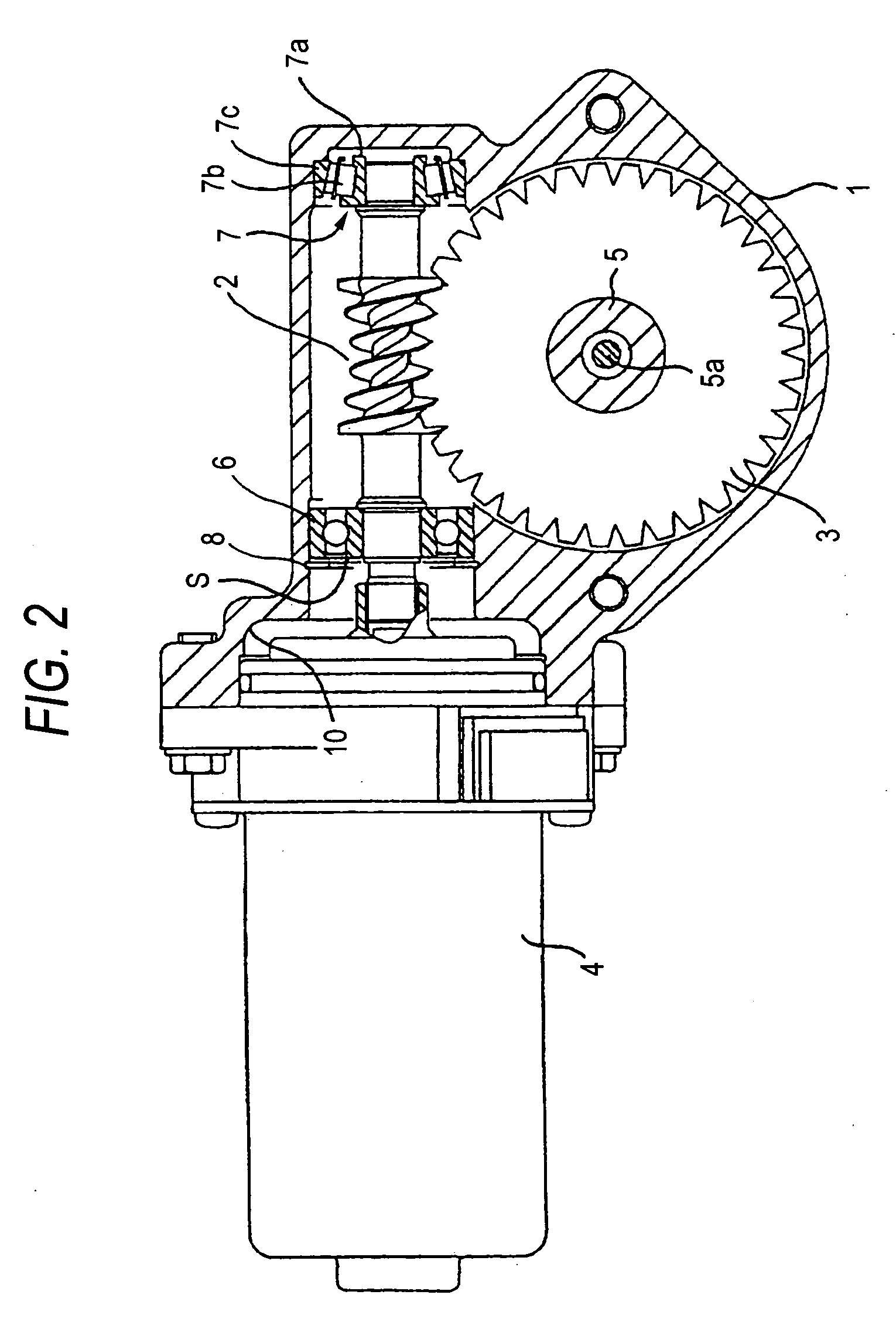
[0112]FIG. 2 is a longitudinal sectional view of an electric power steering according to a first embodiment of the present invention. FIGS. 3A to 3D are schematic views showing a fitting step of the electric power steering according to the first embodiment respectively.

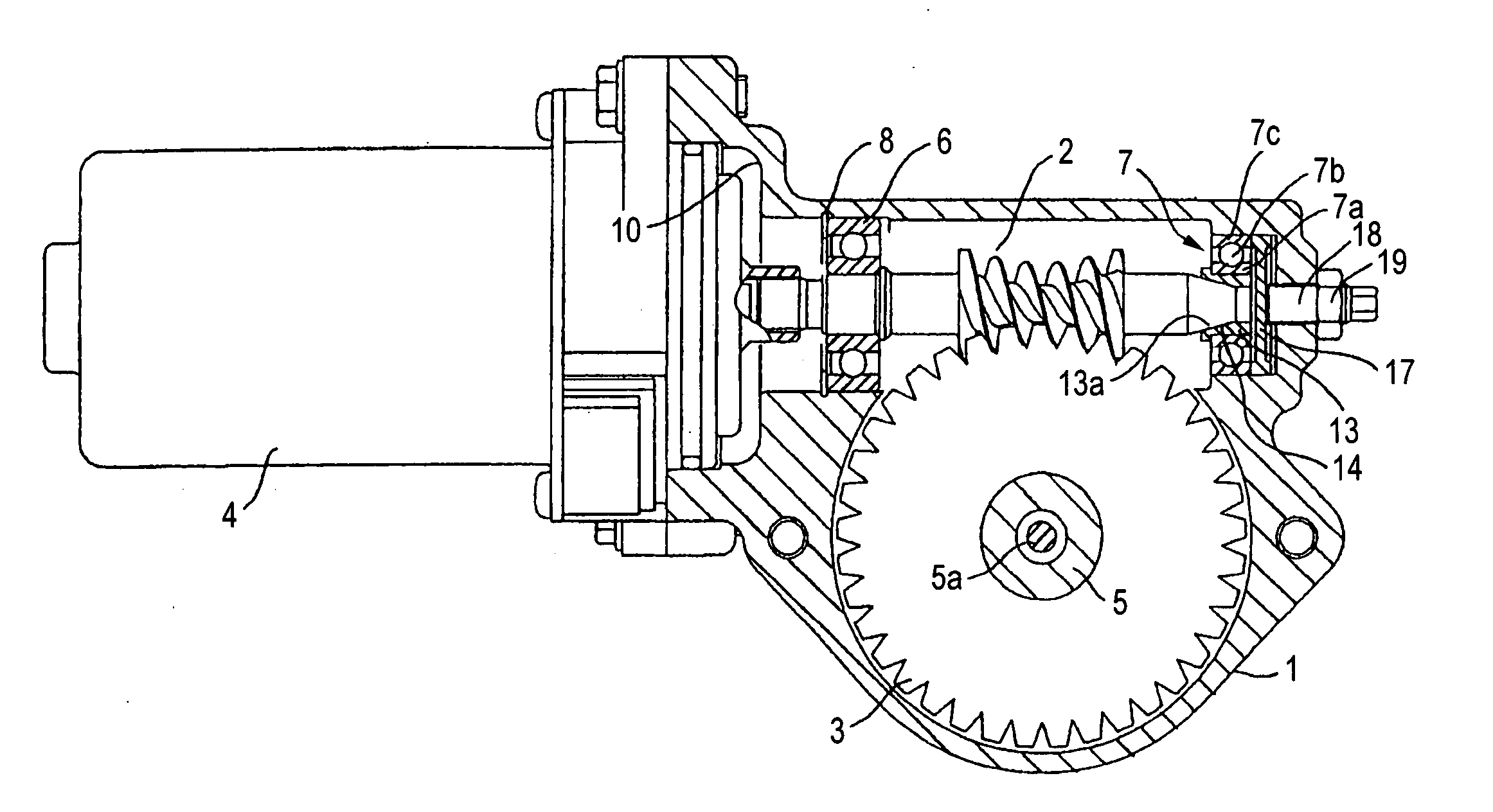
[0113] In the first embodiment, the hourglass worm 2 and the worm wheel 3 that is engaged with the hourglass worm 2 are installed into the gear housing 1 of the worm gear system, and the electric motor 4 for driving the hourglass worm 2 is mounted on the side of the gear housing 1. The worm wheel 3 is fitted onto the output shaft 5 (e.g., the pinion shaft or the column shaft) of the steering equipment. Accordingly, the assist steering torque is generated from the electric motor 4 in response to the steering torque applied to the steering wheel (not shown), and then transmitted the output shaft 5 of the steering equipment via the reduction gear that consists of the hourglass worm 2 and the wheel 3. Here, the reference...

second embodiment

[0120]FIG. 4 is a longitudinal sectional view of an electric power steering according to a second embodiment of the present invention.

[0121] In the second embodiment, the bearing 6 for bearing the motor-side end portion of the hourglass worm 2 is composed of the ball bearing, and is fitted such that its position can be adjusted by using the shim S. In contrast, the bearing for bearing the shaft end portion of the hourglass worm 2 is composed of the angular contact bearing 7 from which the outer ring 7c can be separated and which can support both the radial force and the thrust force.

[0122] In the fitting operation, the inner ring 7a and the rolling elements 7b are fitted to the hourglass worm 2, while the outer ring 7c is fitted beforehand to the gear housing 1. Then, the hourglass worm 2 is moved obliquely to the rotating shaft line of the hourglass worm 2 in the gear housing 1 along the raceway of the outer ring 7c. Thus, the angular contact bearing 7 is assembled in the gear ho...

third embodiment

[0124]FIG. 5 is a longitudinal sectional view of an electric power steering according to a third embodiment of the present invention.

[0125] In the third embodiment, the bearing provided on the shaft end side of the hourglass worm 2 is composed of the deep groove ball bearing 7, and a cylindrical bearing holder 11 having a taper surface 11a on its outer peripheral surface is put on the outer ring 7c of the deep groove ball bearing 7.

[0126] A taper hole 12 with which the taper surface 11a of the bearing holder 11 is engaged is formed in the end portion of the gear housing 1.

[0127] Therefore, in the fitting operation of the hourglass worm 2, the bearing holder 11 is inserted while sliding the taper surface 11a of the bearing holder 11 along the taper hole 12 of the gear housing 1. In other words, the fitting of the hourglass worm 2 into the bearing 7 (deep groove ball bearing) on the shaft end side is applied in the oblique direction to the rotating shaft line of the hourglass worm ...


PUM


Abstract

A subject of the present invention is to provide an electric power steering capable of improving a contact ratio by using an hourglass worm to attain a higher output, and also performing a correction of a misalignment easily by simplifying remarkably a fitting operation of the hourglass worm. A worm gear system causes a hourglass worm 2 driven by an electric motor 4 to mesh with a worm wheel 3 provided to an output shaft 5, and a bearing 7 on the shaft end side, which bears rotatably the hourglass worm 2 is composed of a tapered roller bearing an outer ring of which can be separated. In a fitting operation, an inner ring 7a and rolling elements 7b are fitted into the hourglass worm 2 and also an outer ring 7c is fitted in advance in a gear housing 1. Then, the tapered roller bearing 7 is assembled in the gear housing 1 by moving the hourglass worm 2 obliquely to a rotating shaft line of the hourglass worm 2 in the gear housing 1 along a raceway of the outer ring 7c.

Description

TECHNICAL FIELD [0001] The present invention relates to an electric power steering for generating an assist steering torque from an electric motor in response to a steering torque applied to a steering wheel, and then transmitting the assist steering torque to an output shaft of a steering equipment after a speed reduction using a worm gear system. BACKGROUND ART [0002] In the field of the vehicle steering system, the so-called power steering for giving the steering assist by using the external power source is widely employed. In the prior art, the hydraulic vane pump is used as the power source of the power steering, and is driven by the engine in most cases. However, it was difficult to employ the power steering of this type in a subcompact car of a small engine capacity, etc. because the hydraulic pump must be driven all the time and thus a heavy driving loss of the engine (almost several horsepower to several tens horsepower at the maximum load) is caused. Further, it was unavoi...

Claims


Application Information

Patent Timeline
IPC IPC(8): B62D5/04F16H1/16
CPCB62D5/0409F16H1/16F16H2057/0213F16H55/24
Inventor MAEDA, ATSUSHICHIKARAISHI, KAZUO
Owner NSK LTD
Why Eureka
Try Eureka