
Coated medical devices and methods of making and using

a medical device and coating technology, applied in the field of coatings, can solve the problems of small particulate debris that breaks off and contaminates the synovial fluid, and the device can last a few decades, and achieve the effects of reducing the safety of patients, and reducing the risk of infection

Inactive Publication Date: 2006-08-17
INFRAMAT CORPORATION
View PDF74 Cites 63 Cited by
  • Summary
  • Abstract
  • Description
  • Claims
  • Application Information

AI Technical Summary

Problems solved by technology

Although some devices can last a few decades, a significant number fail within 10 to 15 years.
Localized stress from interaction between these surfaces generates small particulate debris that breaks off and contaminates the synovial fluid surrounding the implant.
However, these enzymes often kill adjacent bone cells or cause osteolysis resulting in mechanical loosening and failure of the implant.
Further, protuberances in a load bearing surface can scratch an opposing load bearing surface, which leads to microcrack formation and ultimately to catastrophic fracture of the implant.

Method used


Image

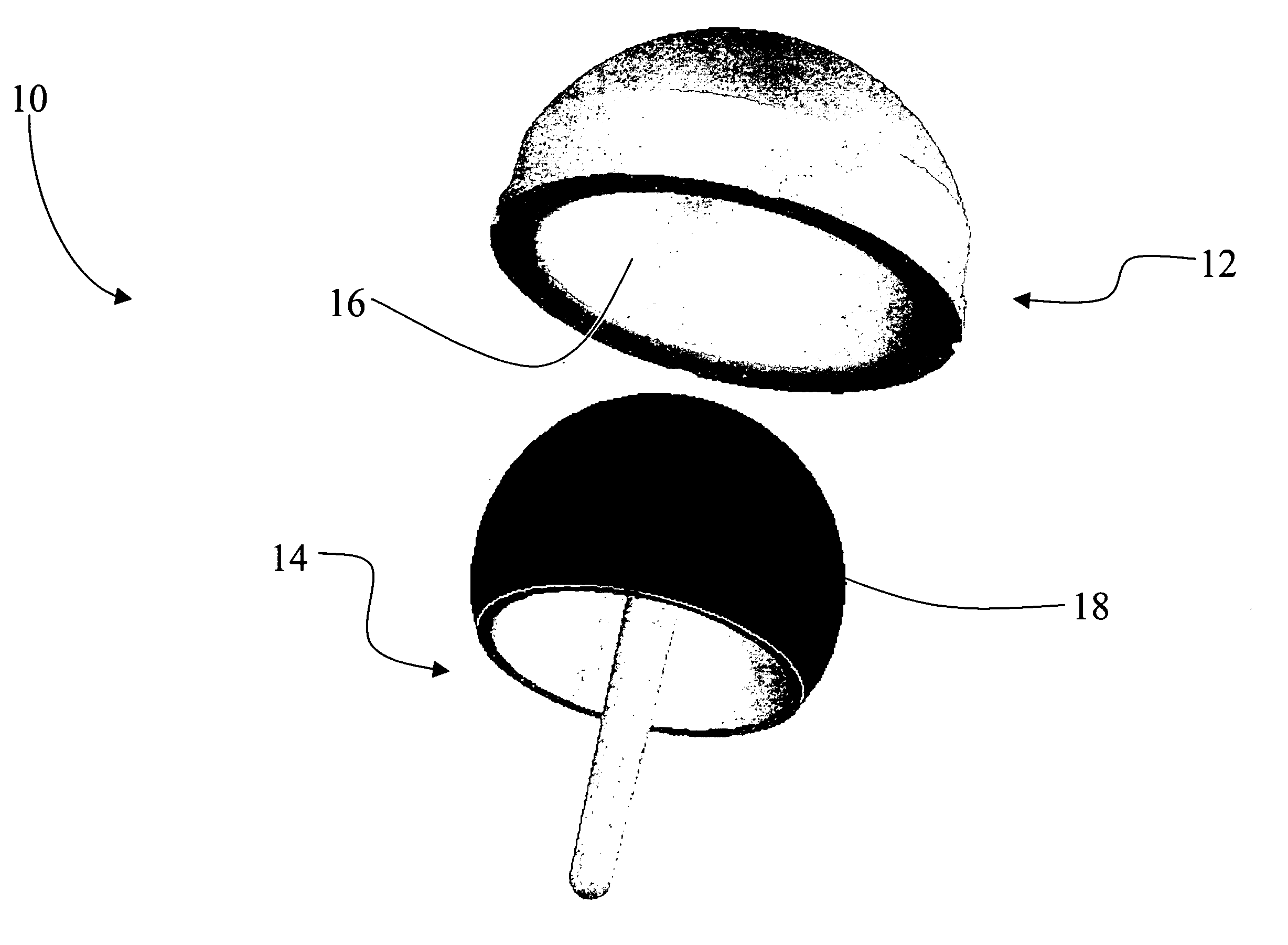
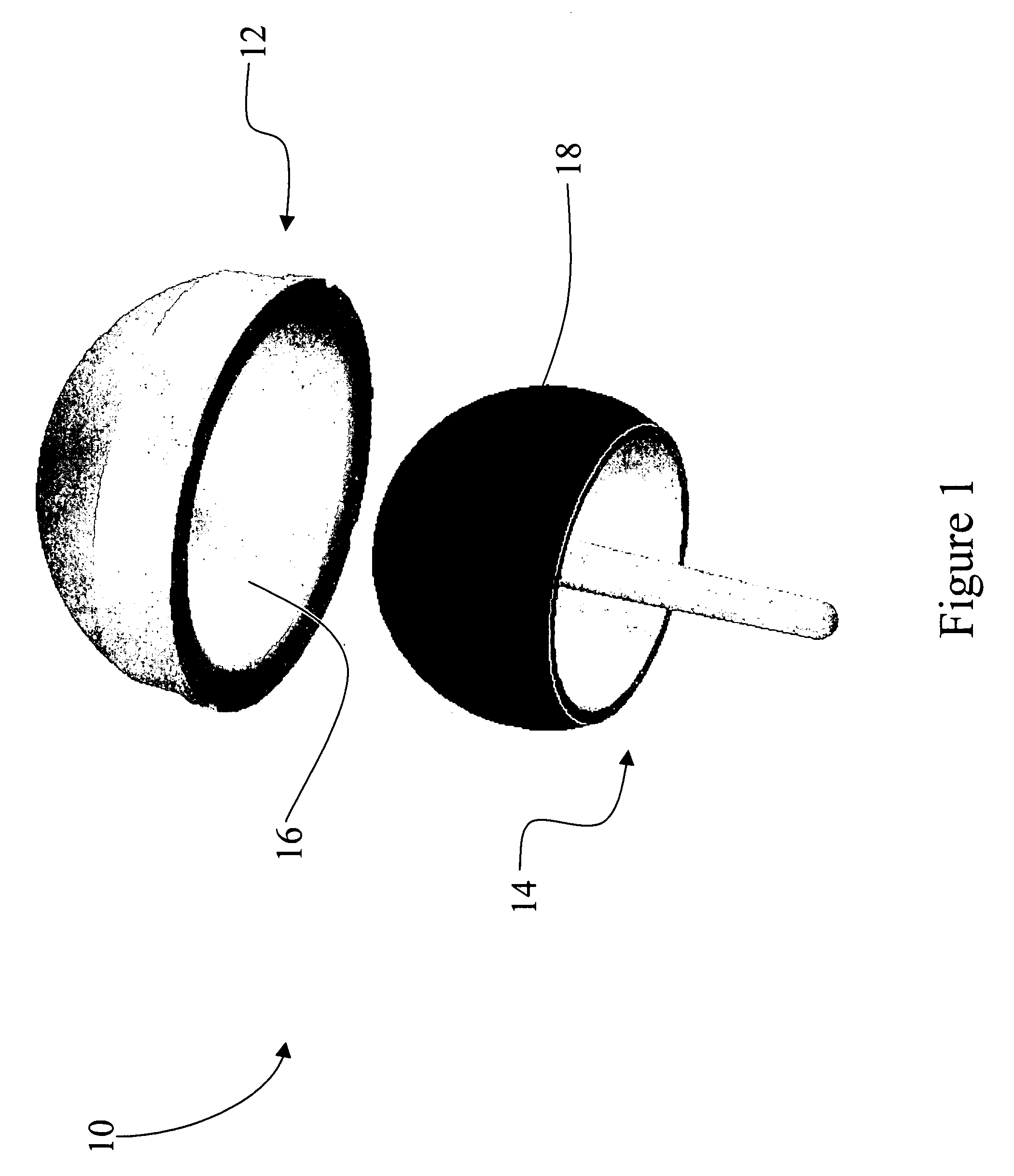
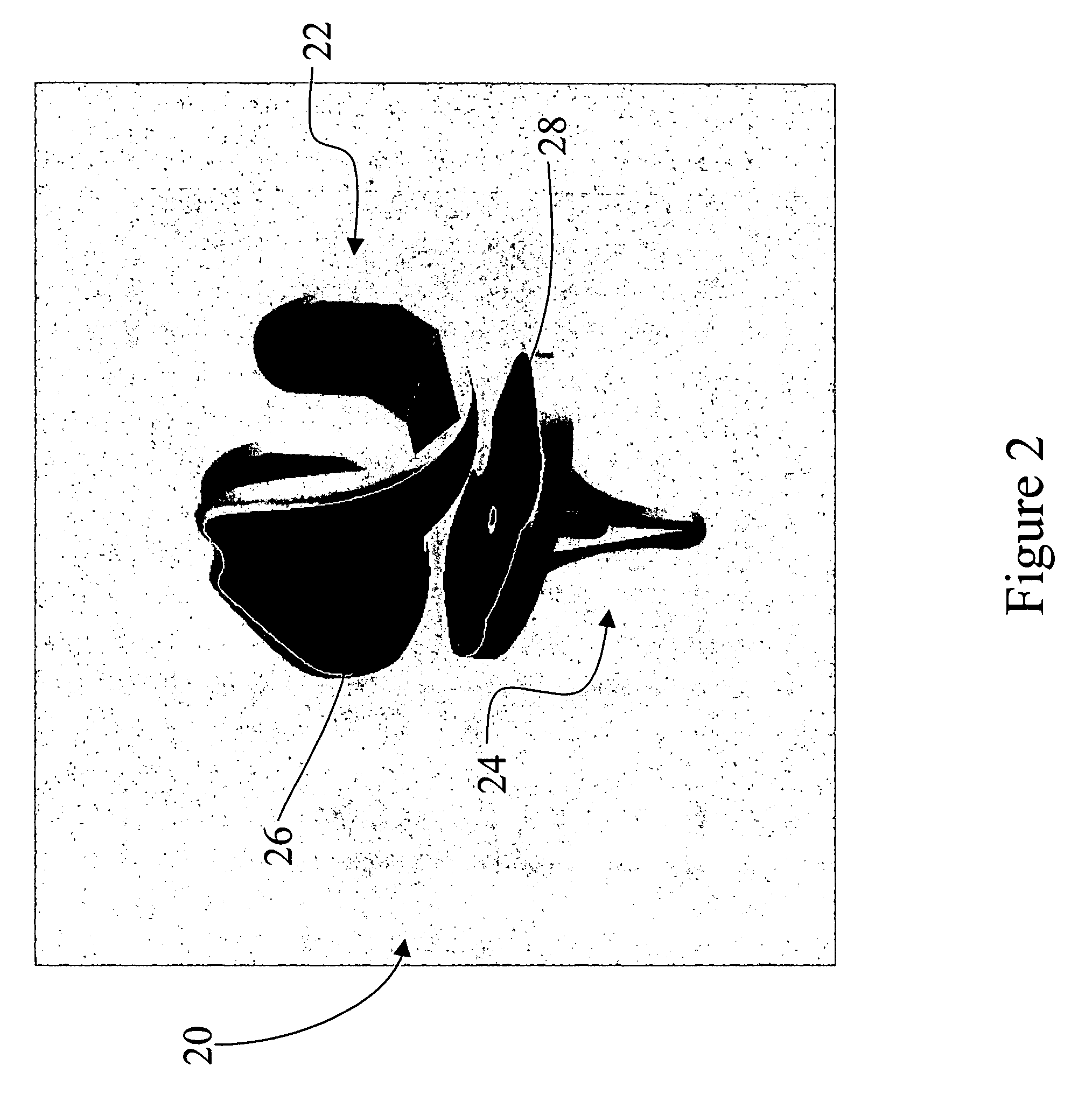
  • Coated medical devices and methods of making and using
  • Coated medical devices and methods of making and using
  • Coated medical devices and methods of making and using

Examples


example 1

Thick Chromia Coated Ti6Al4V Femoral Head

[0049] The chromia feedstock composition contained 5 wt % SiO2 and 3 wt % TiO2, with the balance being Cr2O3. The average particle size of the raw powder materials was about 50 nm for Cr2O3 and SiO2, and about 30 nm for TiO2. A slurry containing the feedstock composition was first prepared with a powder to water ratio of 1:2. The feedstock composition was spray dried using a 16-foot industrial spray dryer with an inlet temperature of 446° F., an outlet temperature of 105° C., and a rotary speed of 25,000 RPM. The spray dried feedstock composition was partially sintered by heating at a temperature below 1000° C. in air, followed by heating at about 1000° C. to 1800° C. in hydrogen to agglomerate the nanoparticles into micrometer sized particles for thermal spraying. The feedstock included individual grains of about 20-50 nm agglomerated into about 5-100 micrometer sprayable agglomerates.

[0050] The feedstock was plasma thermal sprayed using a...

example 2

Comparative

[0054] The chromia coated Ti6Al4V femoral head prepared according to Example 1 was compared to a commercial Co—Cr—Mo alloy on UHMWPE knee joint. As shown in Table 1, the improvements over the commercial product are significant.

TABLE 1Comparison of results for knee jointsCommercially Available Knee JointThick FilmMetal-on-Ceramic coatedCoated JointsEstimatedPropertiesUHMWPEmetal-on-polymerCeramic coatingImprovementsGrain size10-30 μm (Metal)1-5 μm (Ceramic)50 nm˜100 times(Ceramic)Hardness320 (Metal)1200 (Ceramic)1250 (Ceramic)100 timeskg / mm25-13 (UHMWPE)5-13 (UHMWPE)1250 (Ceramic)Friction0.02-0.030.02-0.030.025sameCoeff.Wear5 × 10−7 mm3 / NM2-7 × 10⁻⁸ mm3 / NM3.8 × 0−910-100 timesFactor0.17 mm / year0.13 mm / yearmm3 / NM˜200 timesLinear Rate0.00067mm / yearLongevity10-12 years15 years (estimated)15-25 years5-10 years(estimated)

When converting the volume wear rate to a linear wear rate, the Cr2O3 coating-on-Cr2O3 coating had a linear wear rate of 0.67 μm / year, which was about 200 ...


PUM

PropertyMeasurementUnit
Grain sizeaaaaaaaaaa
Thicknessaaaaaaaaaa

Abstract

A medical device generally includes a structural member having a surface wherein at least a portion of the surface is coated with a nanostructured material to a thickness of at least about 25 micrometers, and wherein the nanostructured material comprises a ceramic, ceramic composite, ceramic metal composite, or a combination comprising at least one of the foregoing. The implants have increased service lifetimes owing in part to improved wear and abrasion resistance, and may be useful for partial or full replacement of articulating and flexible hinge joints.

Description

CROSS REFERENCE TO RELATED APPLICATION [0001] This application claims the benefit of U.S. Provisional Patent Application Ser. No. 60 / 642,449 filed Jan. 7, 2005, which is incorporated herein by reference in its entirety.STATEMENT REGARDING FEDERALLY SPONSORED RESEARCH [0002] The United States Government has certain rights in this invention pursuant to National Science Foundation Grant Number DMI-0319325.BACKGROUND [0003] The present disclosure generally relates to coatings and more specifically to coatings deposited onto surfaces of medical devices. [0004] Surgical implantation of medical devices can structurally compensate for diseased, damaged, or missing skeletal anatomical elements, such as articulating bone joints and related bone structures. Although some devices can last a few decades, a significant number fail within 10 to 15 years. While this may be acceptable for some older patients, longer service lives are needed as younger patients and more active older patients increasi...

Claims


Application Information

Patent Timeline
IPC IPC(8): A61F2/28
CPCA61F2/30767A61F2/30965A61F2/32A61F2/34A61F2/3603A61F2/38A61F2/3804A61F2/40A61F2/4202A61F2/4261A61F2/44A61F2002/30685A61F2002/30838A61F2002/30878A61F2002/30922A61F2002/30934A61F2002/4251A61F2310/00017A61F2310/00023A61F2310/00029A61F2310/00089A61F2310/00203A61F2310/00227A61F2310/00233A61F2310/00239A61F2310/0058A61F2310/00598A61F2310/00604A61F2310/00622A61F2310/00634A61F2310/0067A61F2310/00682A61F2310/00706A61F2310/00718A61F2310/00724A61F2310/0073A61F2310/00736A61F2310/00748A61F2310/00754A61F2310/00766A61F2310/0079A61F2310/00856A61F2310/00862A61F2310/00868A61F2310/00874A61F2310/0088A61F2310/00892A61F2310/00904A61L27/306A61L27/50
Inventor ZHANG, ZONGTAOMA, XINQINGROTH, JEFFREY DAVIDXIAO, T. DANNYKRAJEWSKI, JAY ALEXANDER
Owner INFRAMAT CORPORATION
Learn More