Seat belt retractor with overmolded inertia sensor mass

Inactive Publication Date: 2006-08-17
KEY SAFETY SYST
View PDF17 Cites 6 Cited by
  • Summary
  • Abstract
  • Description
  • Claims
  • Application Information

AI Technical Summary

Benefits of technology

[0006] Like existing seat belt retractor assemblies, a seat belt retractor according to the present invention has an inertial sensor that detects changes in vehicle acceleration. The inertial sensor comprises an inertial sensor mass and a housing that receives the inertial sensor mass. The inertial sensor mass is moveable within the housing to respond to changes in vehicle acceleration. This sensor triggers actuation of a lock of the seat belt retractor. In contrast to conventional designs, the heavy metal inertial sensor mass is at least partially embedded in an elastomeric material. In this way, vibration noise is damped by this material without reducing sensitivity.
[0009] The body of an inertial sensor mass may be suspended in the cavity during the molding process. A support, such as a pin, may hold the inertial sensor mass in place while the polymer is injected into the cavity. If the body of the inertial sensor mass is made of a ferromagnetic material. The support may be magnetized to further secure the body of the inertial sensor mass in place during this process. The polymer may be injected into the cavity of the mold from opposite sides of the inertial sensor mass so that fluid forces from the injection may neutralize each other.

Problems solved by technology

In this way, vibration noise is damped by this material without reducing sensitivity.

Method used


Image

  • Seat belt retractor with overmolded inertia sensor mass
  • Seat belt retractor with overmolded inertia sensor mass
  • Seat belt retractor with overmolded inertia sensor mass

Examples


second embodiment

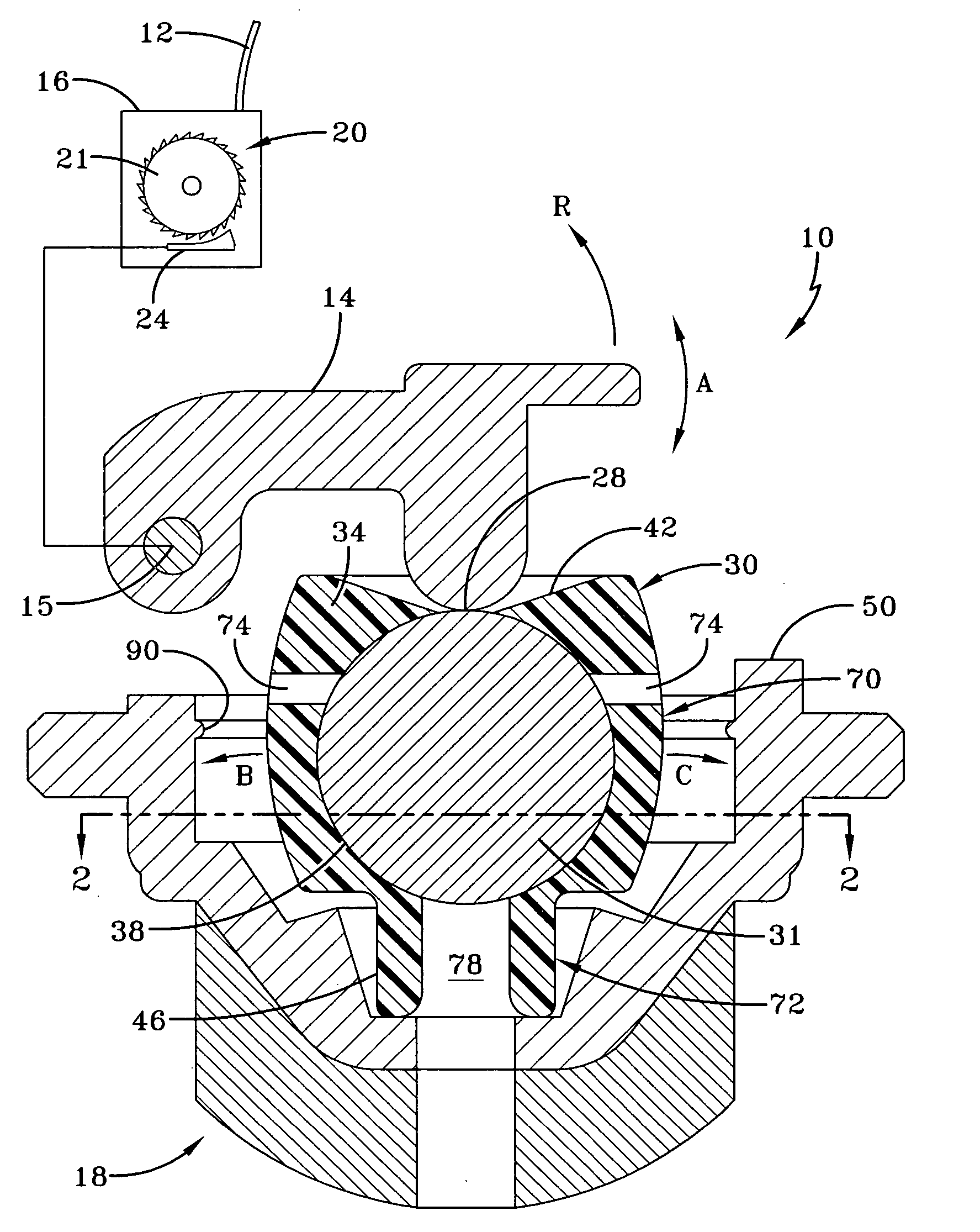
[0030]FIG. 4 is a side view, partially in section, of a seatbelt retractor assembly 10 according to the present invention. Like conventional seatbelt retractors, the seatbelt retractor of the present invention has a seatbelt 12, which is retractable within a seatbelt retractor 10. The seatbelt retractor 10 has a lock 20 which includes an actuator locking pawl 24, which serves to lock and unlock the seatbelt retractor and thereby prevent or allow the seatbelt 12 to extend from a retractor housing frame 16. In addition, the actuator locking pawl 24 is mechanically linked to an actuator arm 14, which serves as a trigger for the actuator locking pawl 24. While the actuator 24 is shown schematically separate from the actuator arm 14, they may form a single piece.

[0031] The actuator arm 14 is pivotable along an arc A. Furthermore, the actuator arm 14 is in contact with an inertial sensor 18 via the top 28 of an inertial sensor mass 26. Inertial sensor mass 26 rests on floor 52 of housing ...

first embodiment

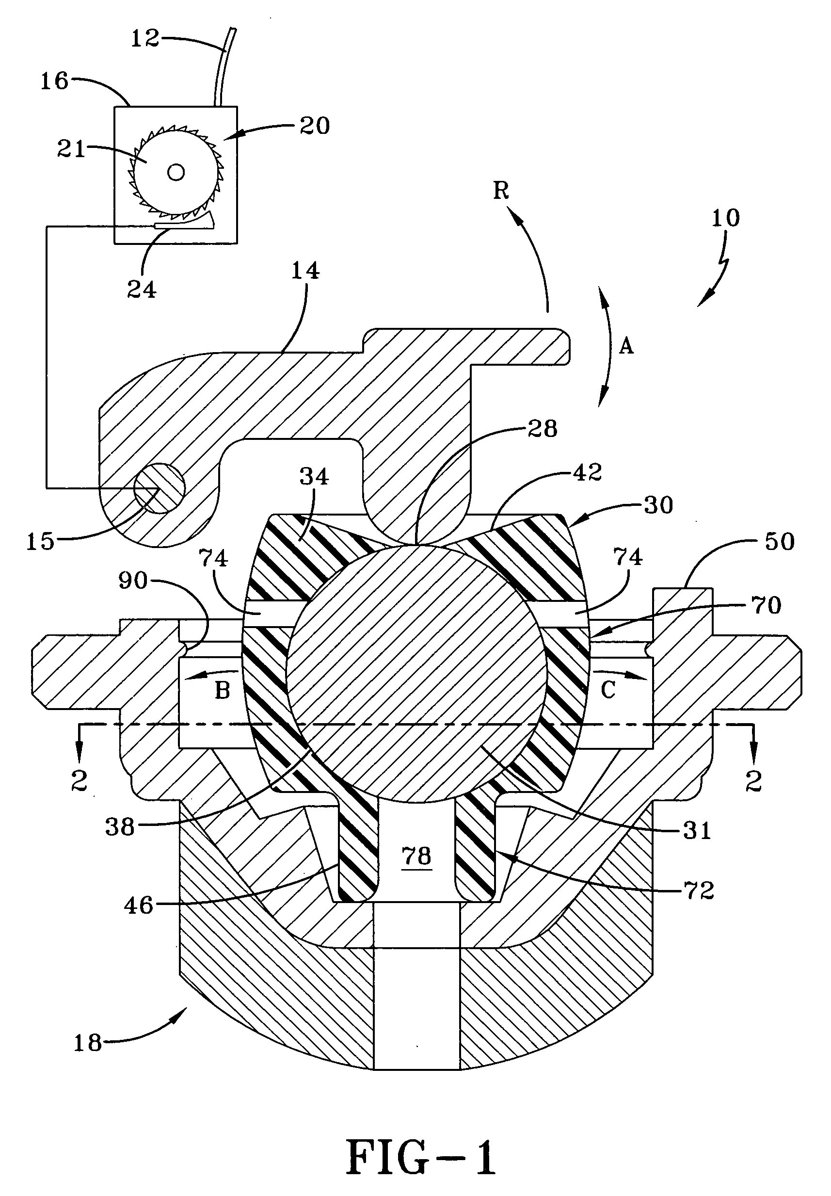
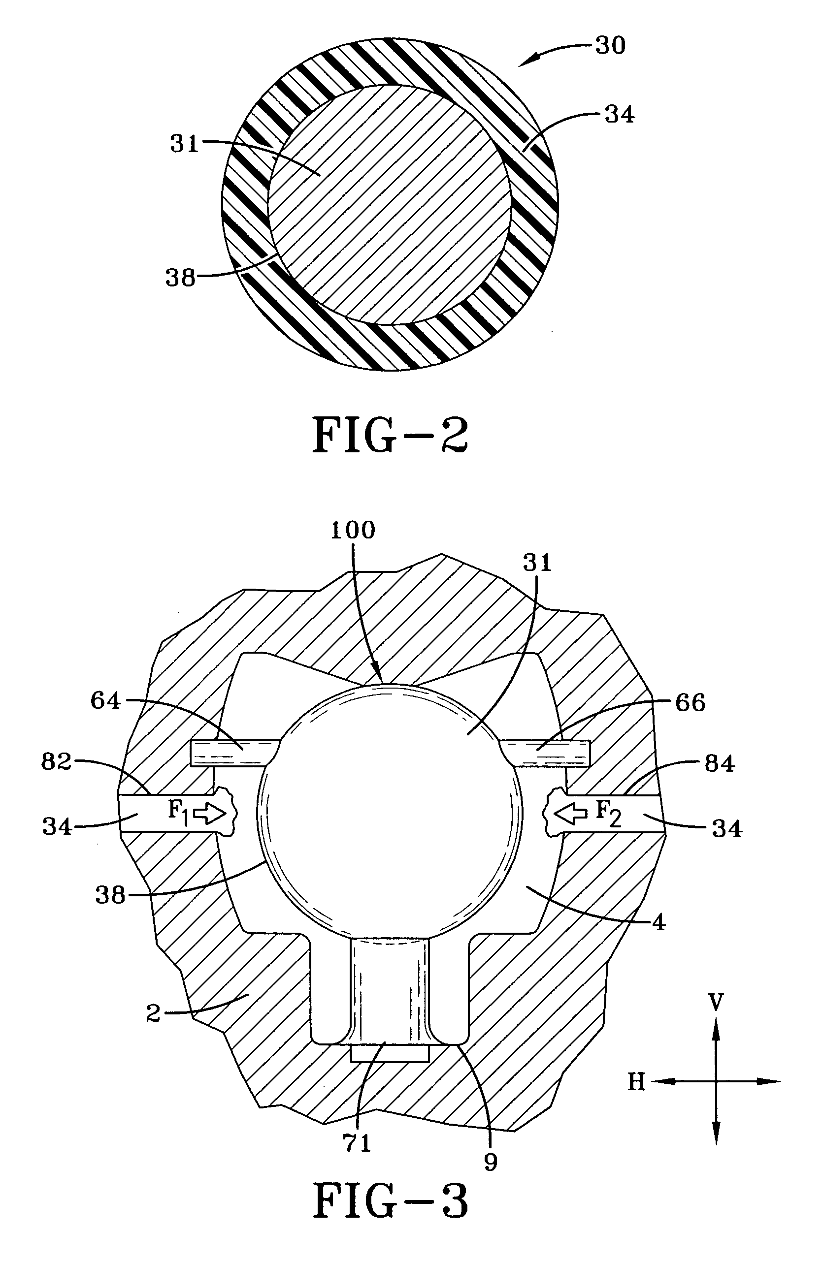
[0033] To further reduce noise and facilitate the manufacture of the first member 54 and second member 58, the inertial sensor mass 26 is preferably made from an elastomeric material 34 with a metal body 31 embedded therein as described in the The metal body 31 provides the appropriate weight to the inertial sensor mass 26 while the elastomeric material 34 serves to cushion vibration and soften contact points. An elastomer with a high density but having sufficient resilience should be used. The elastomer may be ECOMASS™ made by PolyOne, Inc. or THERMOCOMP HSG™ made by LNP Engineering Plastics, Inc. The inertial sensor mass 26 may be cast or molded to create members 54, 58 or alternatively these members can be formed by a cutting operation.

[0034] As shown in FIG. 4, the inertial sensor mass 26 has a wide portion 70 and narrow portion 72. The wide portion 70 has a larger circumference than the narrow portion 72. The first and second members 54, 58 are shown located on the wide portio...

fourth embodiment

[0036]FIG. 7, is a perspective view looking upwards of an inertial sensor mass 29. Like the previous designs, the inertial sensor mass 29 has a narrow portion 70 and a wide portion 72. Unlike the other designs, however, extending from body 31 of the inertial sensor are bristles 65 that extend outwardly from around the body 31 and are generally perpendicular to the surface of the body 31 of the inertial sensor mass 29 as shown in FIG. 7. In this design the individual bristles 65 are surrounded by gaps 62 and protrude outwardly from the inertial sensor mass in a design pattern that insures a first contact of a bristle 65 with the housing. The bristles being spaced and independently movable act like soft springs to deaden the impact or contact noise. The number of bristles contacting the housing depends on the stiffness of the bristles and the rate of acceleration or deceleration.

[0037]FIG. 8 illustrates a fifth version of the inventive inertial sensor mass. An inertial sensor mass 33...


PUM

PropertyMeasurementUnit
Massaaaaaaaaaa
Densityaaaaaaaaaa
Speedaaaaaaaaaa

Abstract

A seat belt retractor (10) has an actuator (14) for unlocking and locking the seat belt retractor (10). An inertial sensor (18) detects changes in vehicle acceleration and interacts with the actuator (14) to lock and unlock the seat belt retractor (10). The inertial sensor (18) has one inertial sensor mass, each mass (26, 27, 29, 30, 32, 33) has a wide portion (70) and a narrow portion (72). Preferably each inertial sensor mass (26, 27, 29, 30, 32, 33) has a high density body (31) embedded in the wide portion (70) of the elastomeric material (34). The inertial sensor mass (26, 27, 29, 30, 32, 33) has a greater density than the elastomeric material (34). Moreover, the elastomeric material (34) at least partially surrounds an exterior circumferential surface (38) of the inertial sensor mass (26, 27, 29, 30, 32, 33). The inertial sensor mass (26, 27, 29, 30, 32, 33) has a body (31) having the wide portion (70) and optionally the narrow portion (72) with preferably one or more elastomeric protruding member (54, 58) extending from said body (31). The one or more protruding members (55, 58) are movable relative to said body (31) and soften contact rattle impacts thus reducing noise.

Description

FIELD OF THE INVENTION [0001] This invention relates to a seat belt retractor. BACKGROUND OF THE INVENTION [0002] A seat belt assembly for a motor vehicle typically has a seat belt retractor that retracts belt webbing onto a spool in a housing. When the belt webbing is drawn or protracted from this housing, the spool winds a retraction spring, which later causes the spool to rotate in an opposite direction to retract the unused portion of the belt webbing back onto the spool. [0003] In a crash, the seat belt retractor has a lock that prevents the belt webbing from extending further from the housing. The lock may be actuated by an inertial sensor, which responds to changes in vehicle acceleration that occur during the crash. When a large change in vehicle acceleration is detected, the inertial sensor triggers the lock of the seat belt retractor to lock the spool against movement and thereby secure the belt webbing in place during the crash. [0004] The inertial sensor has a dense iner...

Claims


Application Information

Patent Timeline
IPC IPC(8): B60R22/40
CPCB29C45/14065B29C45/2708B60R22/40
Inventor MORGAN, CHRISTOPHER D.LIU, HUIYAOVETTER, STEPHAN F.SCHAFFER, KRISTOPHERARNOLD, DAVID R.
Owner KEY SAFETY SYST
Why Eureka
Try Eureka