
Mehtod for producing quartz glass crucible for use in pulling silicon single crystal and quartz glass crucible produced by said method

Inactive Publication Date: 2006-08-10
HERAEUS QUARZGLAS +1
View PDF9 Cites 16 Cited by
  • Summary
  • Abstract
  • Description
  • Claims
  • Application Information

AI Technical Summary

Benefits of technology

[0010] Ordinarily, as for the silica powder to be used for production of the quartz glass crucible, a particle diameter thereof is as fine as 100 to 500 μm, a specific surface area thereof is large due to a nearly spherical shape thereof, and moisture is easily adsorbed on a surface thereof under an environment of high humidity and the thus-adsorbed moisture is fixed in the crucible as an OH group at the time the silica powder is melted, thereby decreasing heat resistance of the crucible. For this reason, in the production method of the quartz glass crucible according to the present invention, the silica powder to be used for production of the quartz glass crucible is held in a gas having a humidity mixing ratio of 0.0005 to 0.0065 kg / kg (dry gas), and preferably 0.001 to 0.0045 kg / kg (dry gas). Examples of Production Methods for Quartz Glass Crucibles Include
[0011] (i) a method comprising the steps of feeding silica powder along an inner peripheral surface of a rotating gas-permeable mold; melting the piled-up layer of the silica powder by heat from a side of the inner peripheral surface of the mold; and, in the process of such melting, suck-discharging gas present in the piled-up layer of the silica powder through a wall of the gas-permeable mold by reducing pressure in an outer peripheral part of the mold, thereby allowing a crucible shape to be formed;

Problems solved by technology

On the other hand, due to such longer time period of work for pulling up the single crystal, heat load put on the quartz glass crucible has increased, thereby causing deformation thereon such that an upper end part of the quartz glass crucible is folded inward or sank (hereinafter referred to simply as “deformation”) in the process of pulling up the silicon single crystal.

Method used


Image

  • Mehtod for producing quartz glass crucible for use in pulling silicon single crystal and quartz glass crucible produced by said method

Examples


example 1

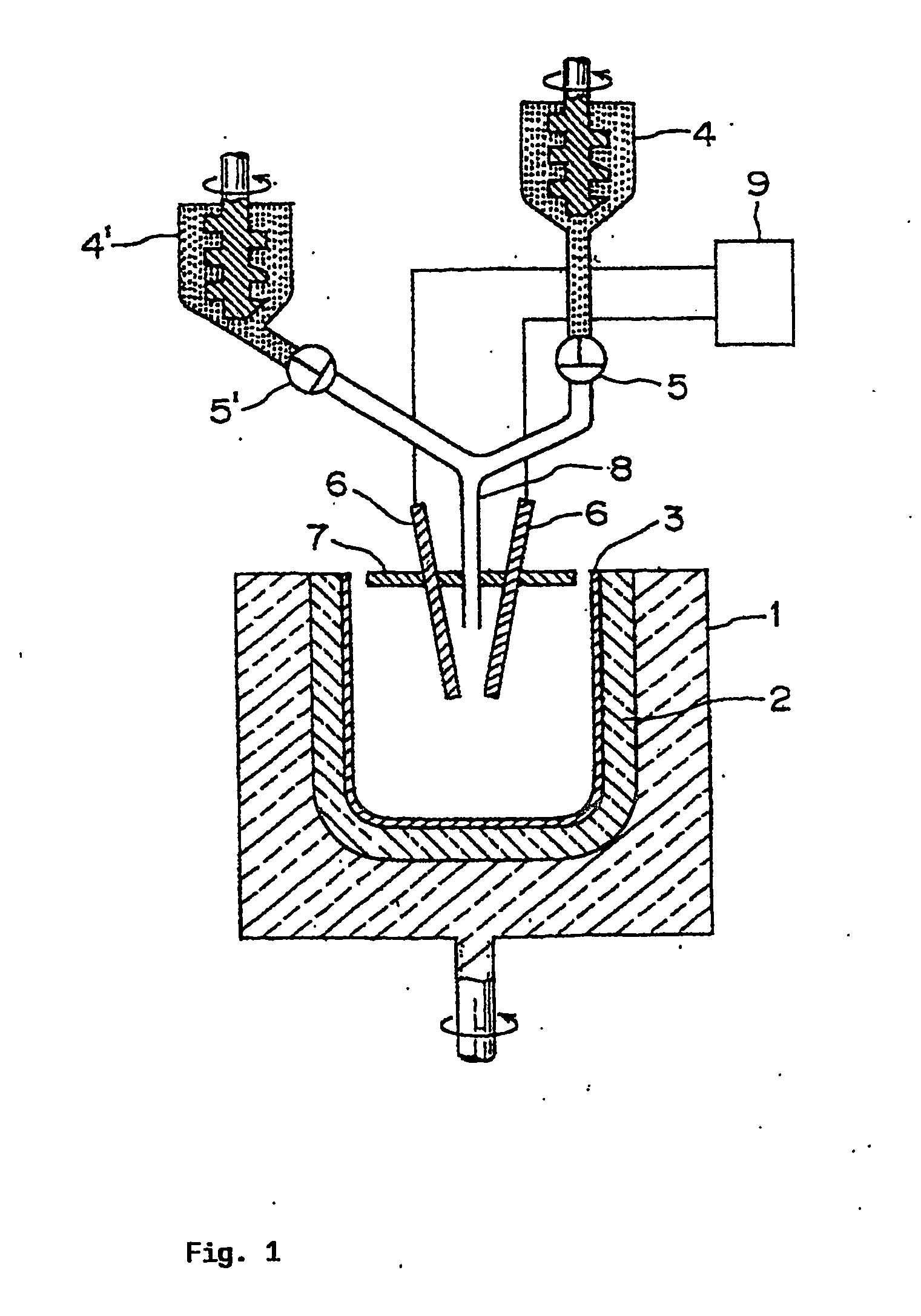
[0017] By using an apparatus as shown in FIG. 1, after an inside of a silica powder storage hopper 4 which stored natural silica powder was held in an atmosphere of air having a moisture mixing ratio of 0.0042 kg / kg (dry air) (10° C., relative humidity: 55%), a flow volume control valve 5 was opened to allow the natural silica powder to be loaded into a rotating mold 1 through a silica powder supply device 8, thereby forming a body in a quartz glass crucible shape by centrifugal force. Thereafter, an arc electrode 6 was inserted in the thus-formed body in the quartz glass crucible shape to allow a cavity of an inner part thereof to be in an atmosphere of high temperature gas, thereby transforming the body into a molten glass state and, then, the resultant body in the molten glass state was cooled to form a translucent quartz glass crucible base body 2. Subsequently, while rotating the mold 1, an inside of the cavity of the quartz glass crucible base body was allowed to be in a high ...


PUM

PropertyMeasurementUnit
Temperatureaaaaaaaaaa
Fractionaaaaaaaaaa

Abstract

The present invention refers to a method for producing a quartz glass crucible for use in pulling silicon single crystal, said crucible having at least a double-layer structure comprising a pore-free transparent inner layer and an opaque base body or outer layer having pores, characterized in that at least the base body is formed with a silica powder maintained in a gas having a mixing ratio of 0.0005 to 0.0065 kg / kg (dry gas), and a quartz glass crucible produced by said production method. The obtained crucible has an average OH group concentration of 50 ppm or lower and is capable of suppressing the vibration occurring on the surface of silicon melt during pulling the silicon single crystal. Further the obtained crucible suffers less deformation of the crucible on pulling the silicon single crystal.

Description

INDUSTRIAL FIELD OF APPLICATION [0001] The present invention relates to a production method for a quartz glass crucible to be used for pulling up a silicon single crystal for semiconductor production. Further the present invention relates to a quartz glass crucible to be obtained by the aforementioned production method. PRIOR ART [0002] Conventionally, in production of a silicon single crystal for semiconductor production, a so-called Czochralski method (CZ method) in which a silicon polycrystal is allowed to be melted in a crucible made of quartz glass and, then, a seed crystal of a silicon single crystal is dipped in the resulting silicon melt and, thereafter, the seed crystal is gradually pulled up while the crucible is rotated to allow the silicon single crystal to be crystalwise grown by using the seed crystal as a nucleus has widely been adopted. It is required that such single crystal to be produced by using the aforementioned CZ method is not only highly pure, but also capab...

Claims


Application Information

Patent Timeline
IPC IPC(8): C03B19/09C30B15/10C03B20/00C30B29/06
CPCC03B19/095C03B2201/04C30B15/10
Inventor OHAMA, YASUOMATSUI, HIROSHI
Owner HERAEUS QUARZGLAS
Learn More