Eureka AIR delivers breakthrough ideas for toughest innovation challenges, trusted by R&D personnel around the world.

Outlet flowing intersecting surface changing adjustable turbo nozzle ring

A turbine nozzle and blade ring technology, which is applied to engine components, combustion engines, machines/engines, etc., can solve the problems of reduced efficiency of the adjustment range turbine stage, difficulty in ensuring the reliability of the structure and operating system, and high price.

Inactive Publication Date: 2008-01-30
孙敏超 +1
View PDF0 Cites 18 Cited by
  • Summary
  • Abstract
  • Description
  • Claims
  • Application Information

AI Technical Summary

Problems solved by technology

The disadvantages are: complex structure, high manufacturing precision, high price, and large volume; long-term work in the environment of high temperature and soot, it is difficult to ensure the reliability of the structure and operating system, and the rotating blades will become stuck, seized and fail
For this reason, it is only applied on the turbocharger of a diesel engine with a relatively low gas temperature, and has not yet been popularized and applied to a turbocharger for a gasoline engine with a higher gas temperature; The high-temperature gas leakage caused by the gap left by the rotating blades will reduce the efficiency of the turbine stage; the adjustment of the angle of the nozzle blade will cause the change of the angle of attack of the impeller inlet airflow and the degree of reaction of the turbine stage. If the adjustment range is too large, the efficiency of the turbine stage will be greatly reduced. decline

Method used


Image

  • Outlet flowing intersecting surface changing adjustable turbo nozzle ring
  • Outlet flowing intersecting surface changing adjustable turbo nozzle ring
  • Outlet flowing intersecting surface changing adjustable turbo nozzle ring

Examples


Embodiment Construction

[0064] Hereinafter, the technical content of the present invention will be further described through the embodiments and in conjunction with the accompanying drawings.

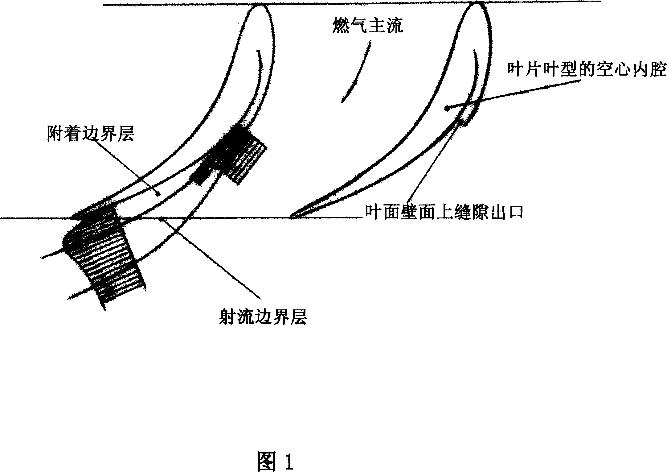
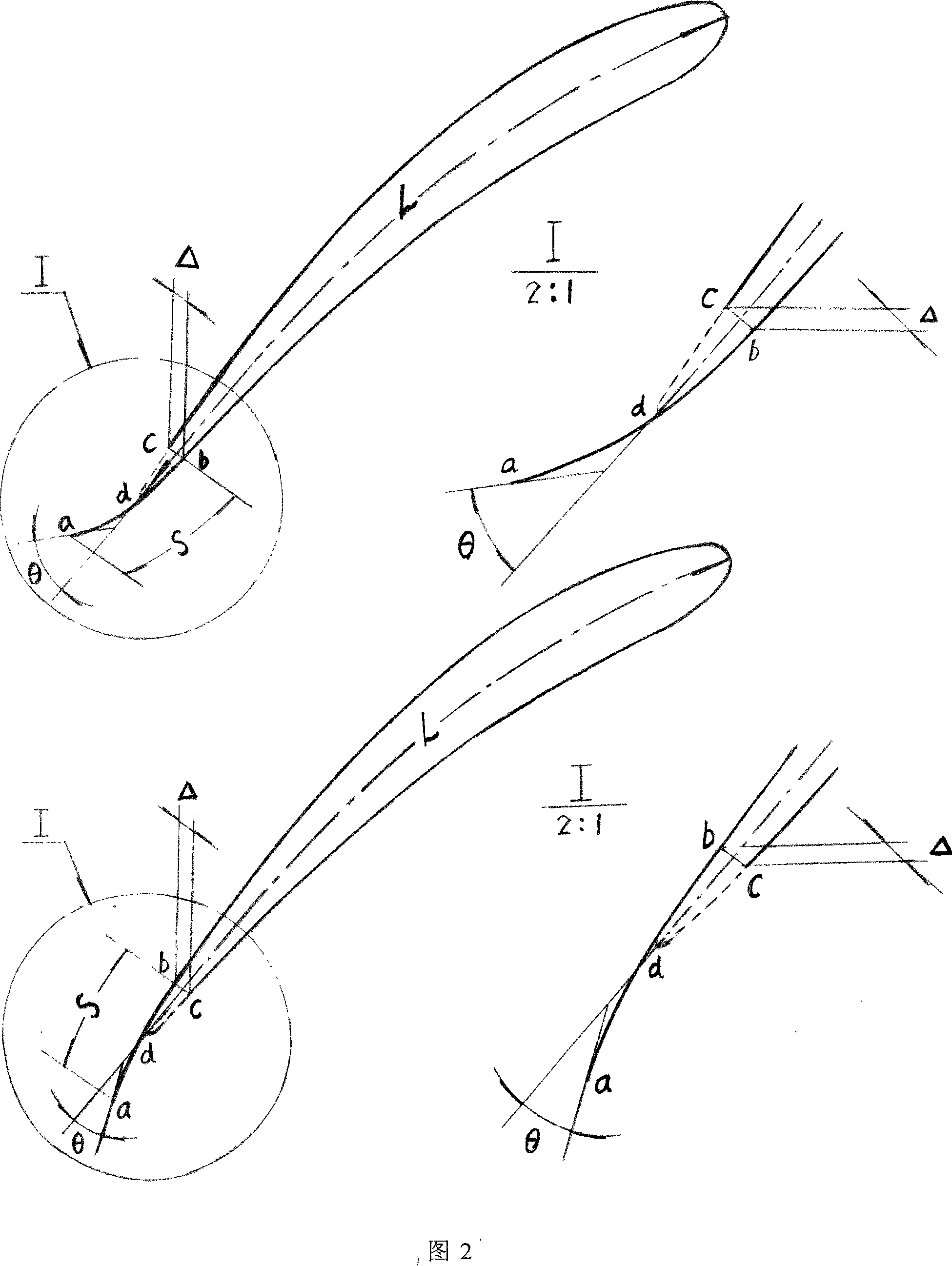
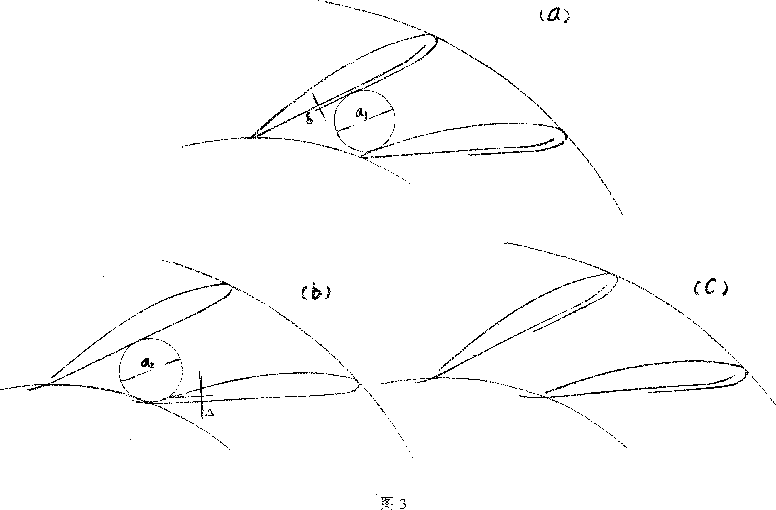
[0065] As mentioned above, the technical core of the present invention is to use externally compressed air to pass through the hollow cavity of the nozzle vane of the turbine nozzle blade ring (vane nozzle) or the cavity at the inner wall of the turbine bladeless volute (blade nozzle ring) inlet pipe. Cavity interlayer, the flow slot cut by the airfoil surface and / or trailing edge of the nozzle blade ring or the annular arc-shaped gap at the outlet of the cavity interlayer at the zero-degree section of the bladeless volute inlet pipe outlet tongue (generally at the tail The edge slot or interlayer outlet gap is equipped with an arc-shaped deflector) and blows the main flow of gas in the flow channel of the nozzle ring cascade and / or the outlet of the cascade along the flow or the main flow of gas flowing out of...


PUM


Abstract

The invention relates to a turbine nozzle ring used in turbochargers. Compressed air from an outlet of an air compressor of the turbocharger and / or an external source goes through a hollow internal cavity of the nozzle vanes or a hollow sandwich near the internal wall of an intake pipe of a vane-less spiral case and blows directly to the nozzle vane ring or main burning gas flow at a flow passage and / or an outlet of the vane-less spiral case through a ventilation groove gap cut between a vane-shaped back side (or front side) and / or a rear margin part or through circular arc-shaped ventilation gap of the outlet of the hollow sandwich near the zero-degree section of the tip of the vane-less spiral case, making the mixed air of blowing flow from the gaps and the main flow change the flow direction at the outlet of the nozzle ring and causing the change of the flow angle (namely flow section) at the outlet. The invention has the advantages of wide range of control simple structure, low cost, safety and reliability, high efficiency, straightforward control and being applicable for turbochargers and being capable of making use of external air, additional pressure and external energy to supply auxiliary power.

Description

technical field [0001] The invention relates to the variable section adjustment technology of a turbine nozzle ring in a turbocharger in the technical field of internal combustion engine turbocharging. Background technique [0002] The use of variable nozzle ring turbine adjustment technology for turbochargers is an effective measure developed in the past two decades to improve internal combustion engine torque reserve and transient response, and reduce fuel consumption and harmful emissions. By changing the flow cross-sectional area of ​​the outlet of the turbine nozzle ring, a good match between the supercharger and the internal combustion engine can be achieved in the full range of operating conditions. , [0003] According to the structure of the turbine nozzle ring, variable nozzle ring adjustment can be divided into nozzle blade ring (turbine nozzle ring cascade composed of nozzle blades, also known as bladed nozzle ring) adjustment and bladeless nozzle ring (bladeles...

Claims


Application Information

Patent Timeline
IPC IPC(8): F01D17/16F02B37/24
CPCY02T10/144Y02T10/12
Inventor 孙敏超孙正柱
Owner 孙敏超
Why Eureka
Eureka Blog
Learn More