
Method and apparatus for sealing flex circuits having heat sensitive circuit elements

a circuit element and heat-sensitive technology, applied in the field of flexible circuits, can solve the problems of limiting the speed or frequency at which the electric components mounted thereto can operate, exposing all of the circuit elements to moisture, chemicals or other contaminants, and flex circuits are thin, light weight, flexible and high-routability. to achieve the effect of adding thermal protection

Active Publication Date: 2006-08-03
HARRIS CORP
View PDF4 Cites 11 Cited by
  • Summary
  • Abstract
  • Description
  • Claims
  • Application Information

AI Technical Summary

Benefits of technology

[0006] This invention is directed to a method and apparatus for affixing an LCP cover layer to a flex circuit consisting of circuit elements mounted to an LCP substrate, at least some of which are temperature sensitive, in order to individually protect the circuit elements from damage and / or reduced operational efficiency due to the presence of moisture, chemical and other contaminants.
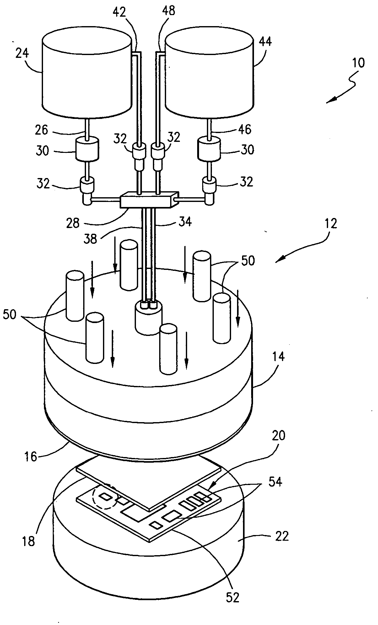
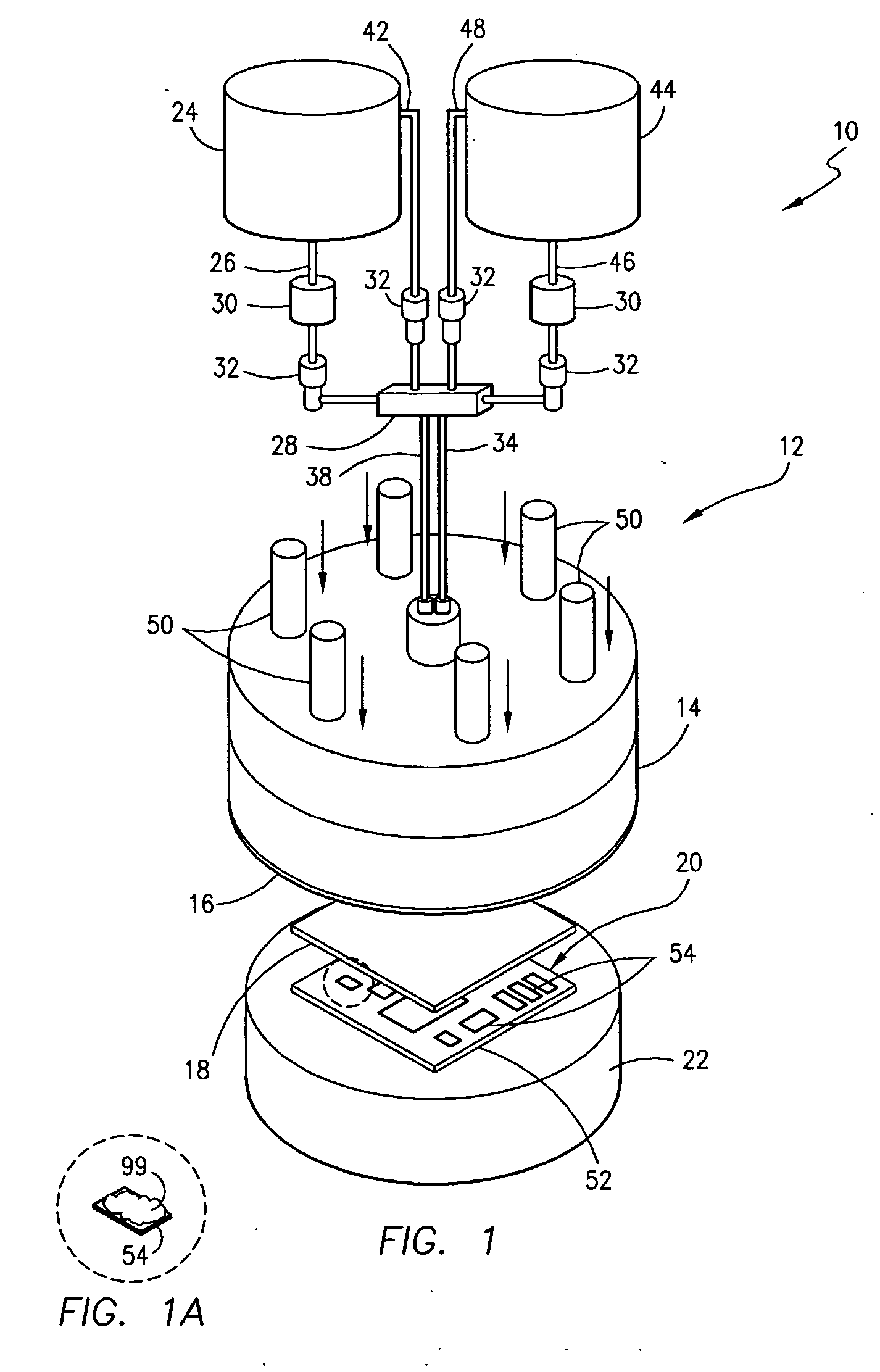
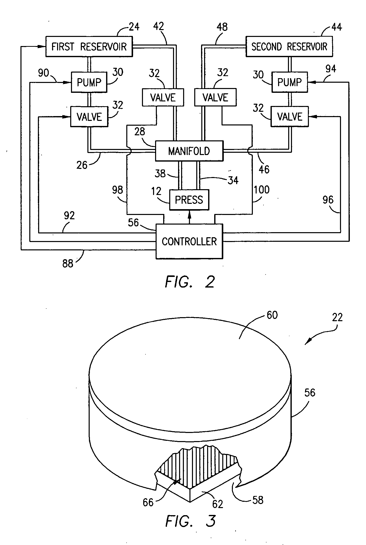
[0008] The flex circuit is placed on the surface of the thermally conductive top plate of a support such that the circuit elements are exposed. A thermal insulating compound may be placed over each temperature sensitive circuit element for added thermal protection. The support includes a housing formed with a cavity within which a number of conduits are mounted each having an upper end communicating with a channel formed in the underside of the top plate. Cooling fluid from a source is circulated through selected conduits, i.e. those which are located beneath the temperature sensitive circuit elements of the flex circuit, to provide localized cooling of such elements during the lamination process. Other conduits, which are not located near the temperature sensitive circuit elements, may be supplied with a heating fluid to raise the temperature of the top plate of the support in selected areas and thus assist with the lamination process.
[0009] With the flex circuit in place on the top plate of the support, and the conduits within the support receiving cooling fluid or heating fluid to cool or heat selected areas of the top plate, an LCP cover layer is placed atop the flex circuit and the press is activated to move into contact with the cover layer. The flexible membrane at the base of the press is capable of substantially conforming to the shape of the circuit elements, thus urging the LCP cover layer around each of them individually to the underlying LCP substrate of the flex circuit. The temperature and pressure applied by the press, and the elevated temperature of selected areas of the support top plate, are sufficient to cause the LCP cover layer and substrate to “relax” or melt to a limited extent and thus adhere together forming a secure bond so that the circuit elements are individually encapsulated between the two layers.

Problems solved by technology

Flex circuits are thin, light weight, flexible and exhibit high routability.
Other properties of polyimide films, however, limit the speed or frequency at which electric components mounted thereto can operate.
A number of problems can arise from this approach.
A failure of the seal between the cover layer and substrate at any point along the periphery of the flex circuit can expose all of the circuit elements to moisture, chemicals or other contaminants.
If the air between the cover layer and substrate is not fully removed, pressurization of the flex circuit which would occur in underwater applications, for example, could compress such air and create a bubble potentially resulting in a rupture of the cover layer and / or substrate thus creating a failure of the entire circuit.
While a number of standard circuit elements are not affected by high temperatures, components such as micro-electrical-mechanical-system (“MEMS”) sensors, infra-red sensors and a variety of other circuit elements are temperature sensitive and can be damaged or destroyed upon exposure to elevated temperatures.

Method used


Image

  • Method and apparatus for sealing flex circuits having heat sensitive circuit elements
  • Method and apparatus for sealing flex circuits having heat sensitive circuit elements
  • Method and apparatus for sealing flex circuits having heat sensitive circuit elements

Examples


Embodiment Construction

[0019] Referring now to the Figs., the apparatus 10 of this invention is schematically illustrated. The apparatus 10 includes an iso-static press 12 having a housing 14 formed with a hollow interior. The base of the housing 14 mounts a flexible membrane 16 having an exposed surface coated with Teflon® or other release agent which will not stick to LCP, and an inside surface coated with a hydrophobic film. Preferably, the flexible membrane 16 is formed of high density polyethylene, butyl rubber, ethylene propylene diene monomer rubber or a similar material.

[0020] The press 12 is operative to apply heat and pressure against a cover layer 18 which overlies a flex circuit 20 placed upon a support 22. In the presently preferred embodiment, the press 12 is heated by the introduction into its hollow interior of heated oil or a similar fluid whose temperature can be relatively accurately controlled and maintained within the range of about 283° C. to 320° C. A first reservoir 24 having heat...


PUM

PropertyMeasurementUnit
temperatureaaaaaaaaaa
melt temperatureaaaaaaaaaa
temperatureaaaaaaaaaa

Abstract

A method and apparatus is disclosed for affixing a cover layer formed of liquid crystal polymer to a flex circuit consisting of circuit elements mounted to a liquid crystal polymer substrate in order to encapsulate the circuit elements between the cover layer and substrate to protect them from exposure to moisture and contaminants and to provide thermal protection of temperature sensitive circuit elements within the flex circuit during the encapsulation process.

Description

FIELD OF THE INVENTION [0001] This invention is directed to flexible circuits, and, more particularly, to a method and apparatus for sealing circuit elements of a flexible circuit, including heat sensitive circuit elements, which are mounted on a substrate formed of liquid crystal polymer to protect them from exposure to moisture and contaminants. BACKGROUND OF THE INVENTION [0002] Flexible or “flex” circuits are used in a wide variety of applications where an electrical circuit must bend around corners or be flexed during operation. Flex circuits are thin, light weight, flexible and exhibit high routability. Traditionally, polyimide films have been used as substrates in the manufacture of flex circuits due to their good thermal stability and mechanical strength. Other properties of polyimide films, however, limit the speed or frequency at which electric components mounted thereto can operate. [0003] Liquid crystal polymer (“LCP”) has been developed in recent years as a replacement ...

Claims


Application Information

Patent Timeline
Patent Type & Authority Applications(United States)
IPC IPC(8): B32B37/00
CPCB32B37/04B32B37/06B32B37/08B32B37/10B32B37/1009B32B37/185B32B2305/55B32B2309/02B32B2457/08H05K1/189H05K3/284H05K2201/064H05K2203/068H05K2203/1121H05K2203/1311H05K2203/304H05K3/30
Inventor SMITH, C.W. SINJINNEWTON, CHARLES M.JAYNES, PAUL B.
Owner HARRIS CORP
Learn More