
Spindle motor having hydronamic pressure bearing

Inactive Publication Date: 2006-07-06
SAMSUNG ELECTRO MECHANICS CO LTD
View PDF5 Cites 5 Cited by
  • Summary
  • Abstract
  • Description
  • Claims
  • Application Information

AI Technical Summary

Benefits of technology

[0025] Therefore, the present invention has been made in view of the above problems, and it is an object of the present invention to provide a spindle motor having a hydrodynamic pressure bearing that is capable of circulating fluid supplied into dynamic pressure grooves, thereby increasing the service life of the fluid and the service life of the motor.
[0026] It is another object of the present invention to provide a spindle motor having a hydrodynamic pressure bearing that is capable of reducing vertical variation between the center of gravity of a rotary body and the center of dynamic pressure, thereby minimizing occurrence of vibration from the motor and improving driving characteristics.
[0027] It is another object of the present invention to provide a spindle motor having a hydrodynamic pressure bearing that is capable of reducing the total weight of the rotary body to decrease inertia when the motor is operated, thereby accurately controlling the speed of the motor.

Problems solved by technology

Generally, a motor having a ball bearing has a problem in that friction occurs between a sleeve of the ball bearing and a shaft of the ball bearing, by which noise and vibration are generated.
Such vibration is called non-repeatable run out (NRRO), which is an obstacle to increasing track density of a hard disk.
However, the position of the oil storing part is high, and the length of a passage connected between the oil storing part and the outside is small.
As a result, the total weight of the rotor 20 is increased, which increases inertia of the rotor 20 when the spindle motor is operated, and therefore, the accurate control of the speed of the spindle motor is difficult, and the impact resistance is lowered.
As a result, the costs necessary to precisely form the dynamic pressure generation grooves G1, G2, and G3 are increased, and therefore, the manufacturing costs of the spindle motor are also increased.
As a result, it is not possible to reduce the height of the spindle motor, and therefore, the miniaturization of the spindle motor is limited.

Method used


Image

  • Spindle motor having hydronamic pressure bearing
  • Spindle motor having hydronamic pressure bearing
  • Spindle motor having hydronamic pressure bearing

Examples


Embodiment Construction

[0061] Now, preferred embodiments of the present invention will be described in detail with reference to the accompanying drawings.

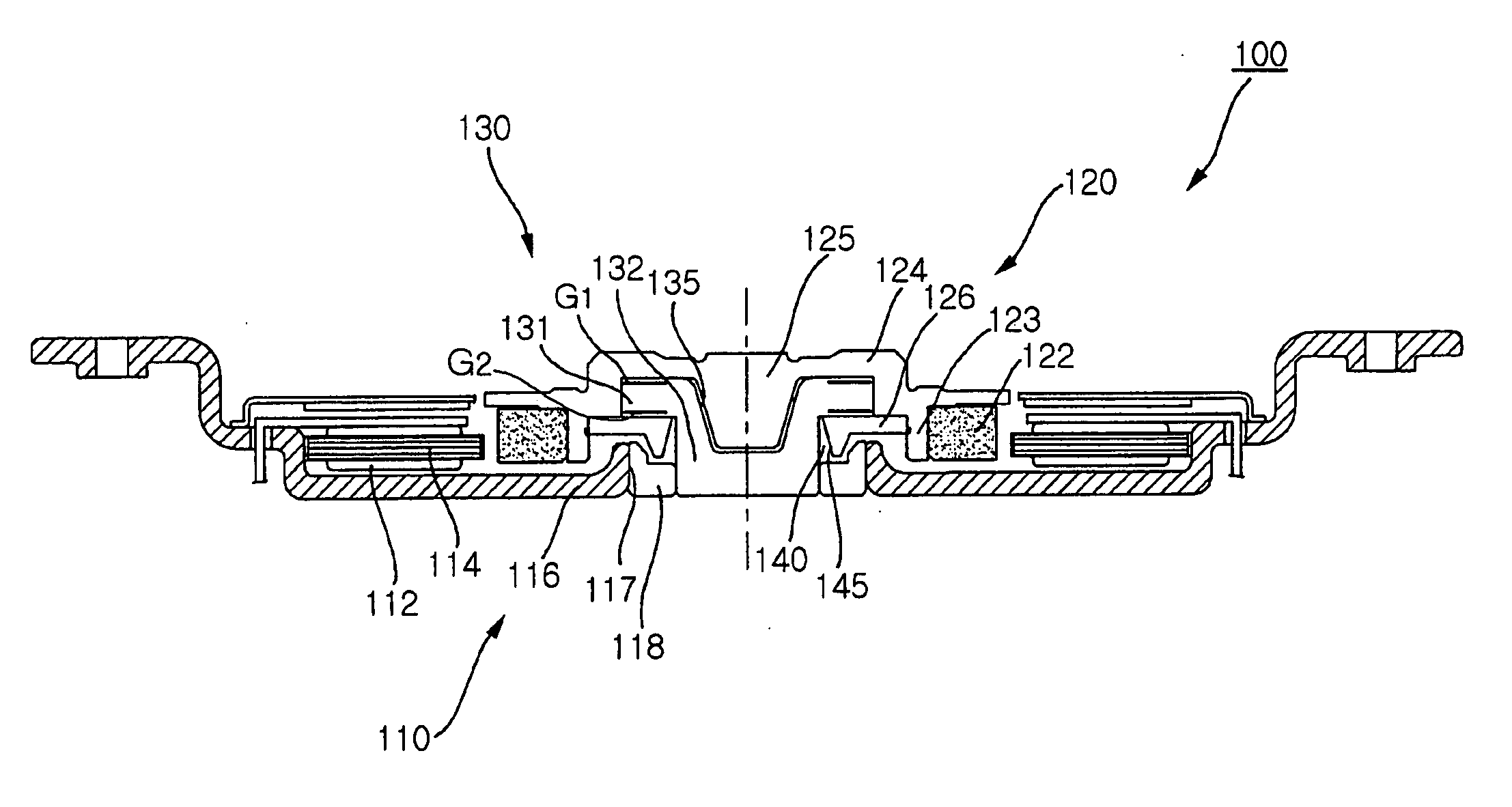
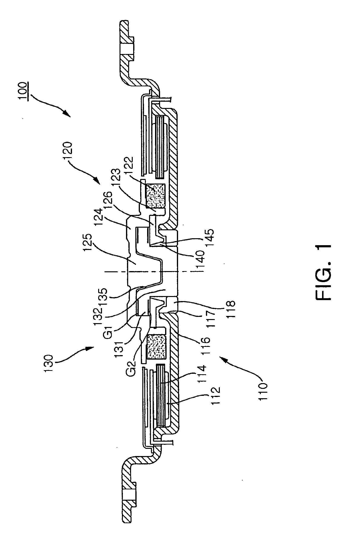
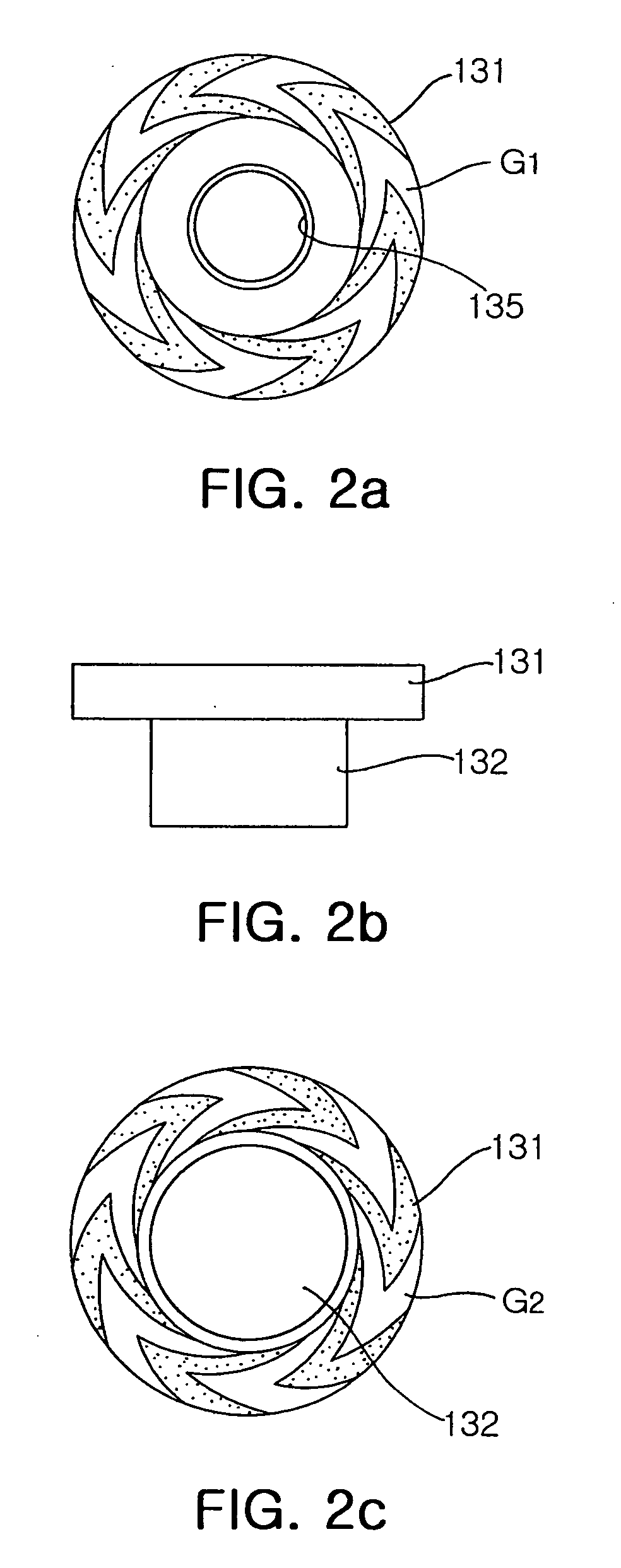
[0062]FIG. 1 is a cross-sectional view illustrating a spindle motor 100 having a hydrodynamic pressure bearing according to a first preferred embodiment of the present invention, FIG. 2A is a plan view illustrating a sleeve of the spindle motor 100 having the hydrodynamic pressure bearing according to the first preferred embodiment of the present invention, FIG. 2B is a front view illustrating the sleeve of the spindle motor 100 having the hydrodynamic pressure bearing according to the first preferred embodiment of the present invention, FIG. 2C is a bottom view illustrating the sleeve of the spindle motor 100 having the hydrodynamic pressure bearing according to the first preferred embodiment of the present invention, and FIG. 3 is a detailed view, in part, illustrating thrust dynamic pressure grooves of the spindle motor 100 having the hydrodynamic pr...


PUM


Abstract

A spindle motor having a hydrodynamic pressure bearing comprises a stator, a rotor, and a dynamic pressure generating unit including a sleeve having an upper plate disposed opposite to the rotor and at least one thrust dynamic pressure groove formed either at the upper plate of the sleeve or at the rotor. Inside width from a neutral radius to an innermost radius of the thrust dynamic pressure groove is larger than outside width from the neutral radius to an outermost radius of the thrust dynamic pressure groove such that the neutral radius is biased to the outside of the thrust dynamic pressure groove. Dynamic pressure at the inside width of the thrust dynamic pressure groove is higher than dynamic pressure at the outside width of the thrust dynamic pressure groove such that fluid supplied into the thrust dynamic pressure groove is guided to the outer diameter side.

Description

RELATED APPLICATIONS [0001] The present application is based on, and claims priority from, Korean Application Number 2005-347, filed Jan. 4, 2005, the disclosure of which is incorporated by reference herein in its entirety. BACKGROUND OF THE INVENTION [0002] 1. Field of the Invention [0003] The present invention relates to a spindle motor having a hydrodynamic pressure bearing, and more particularly to a spindle motor that is capable of circulating fluid supplied into dynamic pressure grooves to increase the service life of the fluid and the service life of the motor, and of reducing vertical variation between the center of gravity of a rotary body and the center of dynamic pressure to minimize occurrence of vibration from the motor and improve driving characteristics. [0004] 2. Description of the Related Art [0005] Generally, a motor having a ball bearing has a problem in that friction occurs between a sleeve of the ball bearing and a shaft of the ball bearing, by which noise and v...

Claims


Application Information

Patent Timeline
IPC IPC(8): F16C32/06
CPCF16C17/045F16C33/107G11B19/2018F16C2370/12A45D34/04A45D40/26B65D83/0033A45D2034/002A45D2040/0006
Inventor JANG, HO KYUNGLIM, TAE HYEONG
Owner SAMSUNG ELECTRO MECHANICS CO LTD
Learn More