
Immersion optical system and optical apparatus having the same

a technology of optical system and optical apparatus, applied in the field of optical system, can solve the problems of na of the optical system not being increased up to na of the optical system not being theoretically increased greater than the refractive index of the glass material,

Inactive Publication Date: 2006-07-06
CANON KK
View PDF0 Cites 10 Cited by
  • Summary
  • Abstract
  • Description
  • Claims
  • Application Information

AI Technical Summary

Problems solved by technology

Therefore, the NA of the optical system cannot be increased up to the refractive index of the glass material.
Moreover, the NA cannot be theoretically increased greater than the refractive index of the glass material.
Thus, the NA cannot be increased up to the refractive index of the glass material.
In addition, in an attempt to increase NA up to the refractive index of the glass material, the light having the maximum incident angle is entirely reflected, and it is thus impossible to make NA of the optical system equal to and greater than the refractive index of the glass material.
Nevertheless, a structure that defines the radius of curvature of the final lens surface, as in the above prior art reference, does not weigh the spread of an area in which the light is irradiated onto the target, and cannot form a good optical image on an entire surface of the light irradiation area, although a good optical image can be obtained at one focal position proportional to λ / NA.

Method used


Image

  • Immersion optical system and optical apparatus having the same
  • Immersion optical system and optical apparatus having the same
  • Immersion optical system and optical apparatus having the same

Examples


numerical example

[0109] A numerical example will now be given of the (concave) final lens surface's radius of curvature r and the distance (liquid thickness) d which enable the maximum NA to be greater than the refractive index nl of the glass material, when the refractive index ni of the immersion material is greater than the refractive index nl of the glass material of the final lens.

[0110]FIG. 10 is a view for explaining the light's refraction in the final lens surface when the final lens's glass material has a refractive index of ni, the immersion material has a refractive index of ni (>nl), and the final lens surface has a radius of curvature of r.

[0111] The Snell's law defines the light's refraction at the interface. FIG. 10 shows that a ray 1 from the lens is incident upon a final concave surface at an angle θ1 relative to a surface normal of the final concave surface, is refracted on the final concave surface, is turned to a ray 2 at an angle θ2 relative to the surface normal, and reaches ...

second embodiment

[0131] While the first embodiment describes the immersion optical system used for a projection optical system in a semiconductor exposure apparatus, the inventive immersion optical system is applicable to another optical system in an optical apparatus, such as an optical disc drive, a laser microscope, which optically records information and reproduces recorded information.

[0132] Referring now to FIG. 17, a description will be given of an immersion optical system used for an objective optical system in a laser microscope 300. In the laser microscope 300, a laser beam 300 emitted from a light source 301 transmits a beam splitter 302 and is scanted by an X-Y scanning optical system 303. The scanned beam 3130 is reflected on a mirror 304, and then irradiated on a target 307 to be observed. An immersion material 306 is filled in a space between a final lens surface 305a and the target 307 in the objective optical system 305, and the beam 310 is emitted and converged from the final lens...


PUM


Abstract

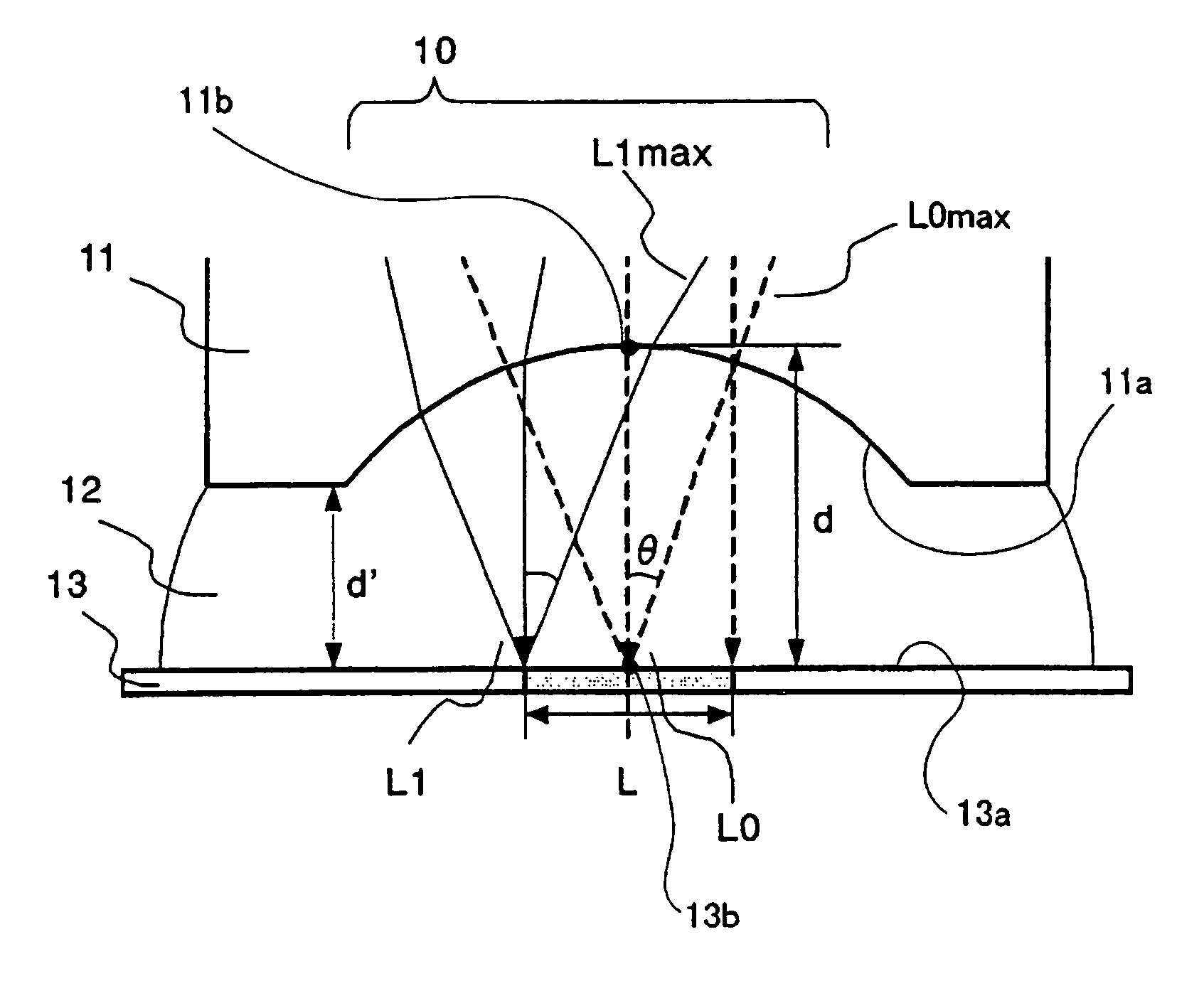
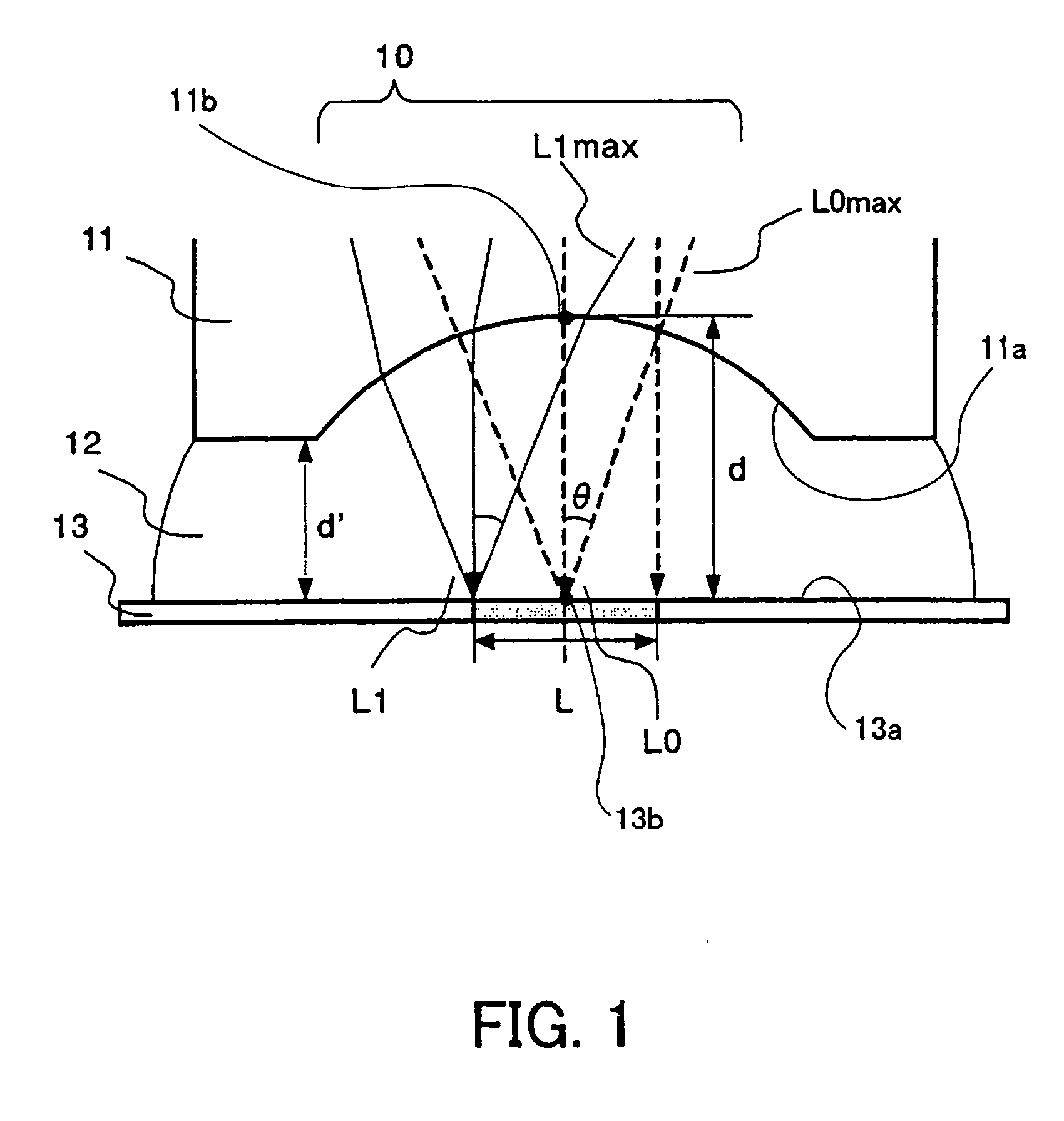
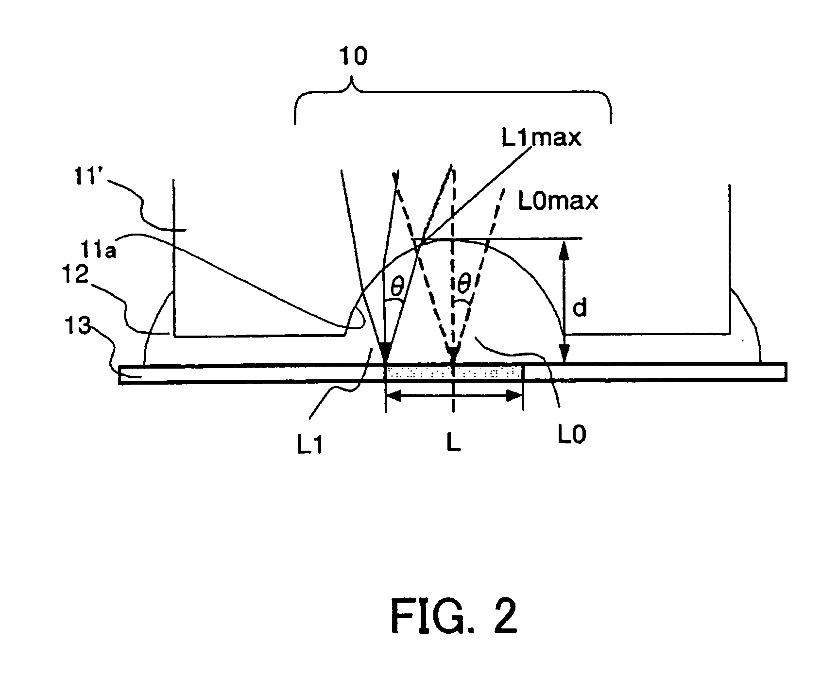
An immersion optical system that condenses light from a light source toward a first surface includes a lens having a concave lens surface closest to the first surface, a liquid being filled in a space between the concave lens surface and the first surface, wherein a conditional equation d>L / [2×tan {arcsin(NA / ni)}] is met, where d is a distance between a first point and a second point when the distance becomes maximum between the first point on the concave lens surface and the second point on the first surface in a direction substantially orthogonal to the first surface, L / 2 is a maximum distance from the second point to an edge of an irradiation area of the light on a first surface, NA is a numerical aperture of the immersion optical system, and ni is a refractive index of the liquid.

Description

BACKGROUND OF THE INVENTION [0001] The present invention relates generally to an optical system that converges the light from a light source onto a target, and more particularly to an immersion optical system that fills a liquid between a final lens surface and a target and an optical apparatus having the immersion optical system. [0002] For an improved resolution of an optical system, such as a microscope and a semiconductor exposure apparatus, the immersion lithography is used which fills an immersion material having a refractive index greater than 1 in a space between a target and a final lens surface of an optical system and improves an effective numerical aperture (“NA”). The final lens surface of the optical system for the immersion lithography is often designed to a plane for filling easiness of the immersion material in the space. [0003]FIG. 18 shows an optical system that uses the conventional immersion lithography. The optical system includes a final lens 201 and an immers...

Claims


Application Information

Patent Timeline
IPC IPC(8): G11B7/00
CPCG02B21/33G03F7/70241G03F7/70341G11B7/1374
Inventor OHKUBO, AKINORIHONDA, TOKUYUKIMORISHIMA, HIDEKI
Owner CANON KK
Learn More