Solid electrolytic capacitor

Active Publication Date: 2006-07-06
SANYO ELECTRIC CO LTD +2
View PDF4 Cites 2 Cited by
  • Summary
  • Abstract
  • Description
  • Claims
  • Application Information

AI Technical Summary

Benefits of technology

[0011] It is therefore an object of the present invention to provide a solid electrolytic capacitor which includes an anode having a greater capacitance and, particularly, to provide a solid electrolytic capacitor having a lower rated voltage.

Problems solved by technology

However, the inventor has found that the cathode foil 5 having such a structure is less effective for increasing the capacitance of the solid electrolytic capacitor 1.
However, the dielectric film formed by the direct oxidization of the surface of the titanium base is liable to be aged over time.
That is, it is difficult to form a stable titanium oxide film on the surface of the titanium anode base.

Method used


Image

  • Solid electrolytic capacitor
  • Solid electrolytic capacitor

Examples


Embodiment Construction

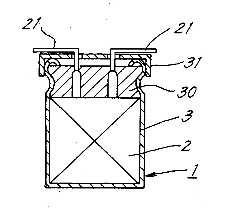
[0017] One embodiment of the present invention will hereinafter be described in detail with reference to the attached drawings.

[0018] A solid electrolytic capacitor 1 has substantially the same overall construction as the prior art capacitor shown in FIG. 2. As shown in FIG. 1, a capacitor element 2 includes an anode foil 4 of an aluminum foil having an electrochemically formed film and a cathode foil 5 of an aluminum foil, which are rolled together into a roll with an insulative separator 6 interposed therebetween and fixed by a tape 26. The capacitor element 2 is impregnated with a solid electrolyte such as a TCNQ complex salt, or includes an electrically conductive polymer layer provided therein. A pair of lead wires 21, 21 extend from the capacitor element 2.

[0019] The capacitor element 2 is produced in the following manner. First, an aluminum foil strip for the anode foil 4 is cut out of an aluminum sheet, and etched. The surface of the aluminum foil is roughened by the etchi...


PUM

PropertyMeasurementUnit
Dielectric polarization enthalpyaaaaaaaaaa
Electrical conductivityaaaaaaaaaa

Abstract

A solid electrolytic capacitor comprises a capacitor element which includes an anode foil and a cathode foil rolled with a separator interposed therebetween, and a solid electrolyte layer or an electrically conductive polymer layer provided therein. The anode foil is coated with a dielectric oxide film. The dielectric oxide film is an oxide film formed by oxidizing a film of a mono-metal nitride or a composite metal nitride formed on the anode foil. The mono-metal nitride is titanium nitride, zirconium nitride, tantalum nitride or niobium nitride. The composite metal nitride is aluminum titanium nitride, chromium titanium nitride, zirconium titanium nitride or titanium carbonitride.

Description

TECHNICAL FIELD [0001] The present invention relates to a solid electrolytic capacitor which includes an anode foil and a cathode foil rolled together. BACKGROUND ART [0002]FIG. 2 is a sectional front view of a prior art solid electrolytic capacitor 1, and FIG. 1 is a perspective view of a prior art capacitor element 2 (see, for example, Japanese Examined Patent Publication No. HEI4-19695 (1992)). [0003] The solid electrolytic capacitor 1 includes an aluminum case 3 having a top opening, the capacitor element 2 contained in the case 3, and a rubber packing 30 which seals the opening of the case 3. An upper edge portion of the case 3 is curved to fix the packing 30, and a plastic seat plate 31 is attached to the top of the case 3. Lead wires 21, 21 extend from the capacitor element 2 through the packing 30 and the seat plate 31, and then bent laterally. [0004] As shown in FIG. 1, the capacitor element 2 includes an anode foil 4 of an aluminum foil coated with a dielectric oxide film ...

Claims


Application Information

Patent Timeline
IPC IPC(8): H01G2/12H01G9/00H01G9/025H01G9/028H01G9/04H01G9/042H01G9/055H01G9/14H01G9/15
CPCH01G9/0032H01G9/028H01G9/042Y10T29/41H01G9/151Y10T29/417H01G9/055H01G9/04H01G9/025H01G9/15
Inventor YOSHIMITSU, SATORUFUJIMOTO, KAZUMASASAITO, HIROMUYOSHIDA, YASUSHI
Owner SANYO ELECTRIC CO LTD
Why Eureka
Try Eureka