Media cartridge storage device for an autoloading data storage and retrieval system

Inactive Publication Date: 2006-07-06
IBM CORP
View PDF15 Cites 14 Cited by
  • Summary
  • Abstract
  • Description
  • Claims
  • Application Information

AI Technical Summary

Benefits of technology

[0014] The present disclosure describes a novel apparatus for storing data cartridges, e.g., tape cartridges, within a data storage and retrieval system, e.g., a tape library. The disclosure describes a cartridge storage device designed to fit in an unused drive slot. The apparatus is capable of storing a number of data cartridges, with each cartridge stored on a transport mechanism that feeds the cartridge to the front of the apparatus for access by the system picker. By storing the cartridges in this fashion, the depth of the drive slot can be maximized for storing tape cartridges.
[0015] Accordingly, data cartridges can be stored in removable and “hot swappable” cartridge storage devices which can be placed into a drive slot to increase the amount of storage in an automated tape library. Since the depth of the drive slot is much deeper than a normal storage slot, this mechanism allows for data cartridges to be stored at a depth not previously available in a tape library. This mechanism also provides a means for the data cartridge to be moved from the full depth of the drive slot to the front of the drive slot where the cartridge can be accessed by the picker.
[0016] One of the many advantages of this invention is that the storage capacity of the library can be increased utilizing the existing empty space within the library. For instance, in an IBM 3584 D32 library frame with no drive canisters and 12 cartridge storage devices the storage capacity of the library can increase by 52 cartridges, or 12%. Another advantage of the cartridge storage device over the filler panel is that filler panels are currently used to cover 4 drive slots. If one drive canister is in place, three empty drive slots do not have any storage slots. The cartridge storage devices could fill these empty drive slots in any combination which adds flexibility and scalability of storage. In this particular case the cartridge storage devices could increase the library storage by 61 cartridges or 14%. In other libraries that have filler panels that cover 10 drive slots, one drive can create nine unused drive slots which could be filled with cartridge storage devices providing 72 more cartridges to the library.

Problems solved by technology

A challenge in the design of storage libraries is to maximize storage density while maintaining flexibility and scalability.
Very often it is found that users do not populate all of the drive slots available.
However, when this happens all of the other space behind the panel where a drive could be located becomes unused and empty.
Additionally, it is currently not possible to store tape cartridges in the unused drive slots, thus the unused drive slot is wasted space.
There are limitations with the way that I / O stations are currently used today: I / O stations have a defined location in a frame, e.g., in one tape library, the I / O stations are only allowed in a specific frame at one end of the library.
Also, these I / O stations consume a large amount of storage space within the library, e.g., in one library, addition of 30 I / O slots causes the library to lose 80 storage slots.
An additional drawback is that these I / O stations are not easily serviceable.
Also the scalability of I / O stations is limited.
This is a disruptive activity as the automated data storage library must be paused or stopped during the addition or removal of the magazines.
The conversion requires that the library door be opened and this disrupts normal library operation.
In addition, tools are required to perform these conversions and this process usually requires a trained service technician.
However, there are several drawbacks to this system.
One drawback is that the magazine must be positioned alongside the drive, and so the magazine is not truly modular.
Another drawback is that tapes are loaded / unloaded from the side, so the magazine must be physically removed from the library to load it.
This makes the picker unavailable for other applications during that time.
A further drawback is that users cannot see which tapes are in the magazine without physically removing the magazine from the library and then physically removing the tapes.

Method used


Image

  • Media cartridge storage device for an autoloading data storage and retrieval system
  • Media cartridge storage device for an autoloading data storage and retrieval system
  • Media cartridge storage device for an autoloading data storage and retrieval system

Examples


Embodiment Construction

[0036] The following description is the best embodiment presently contemplated for carrying out the present invention. This description is made for the purpose of illustrating the general principles of the present invention and is not meant to limit the inventive concepts claimed herein.

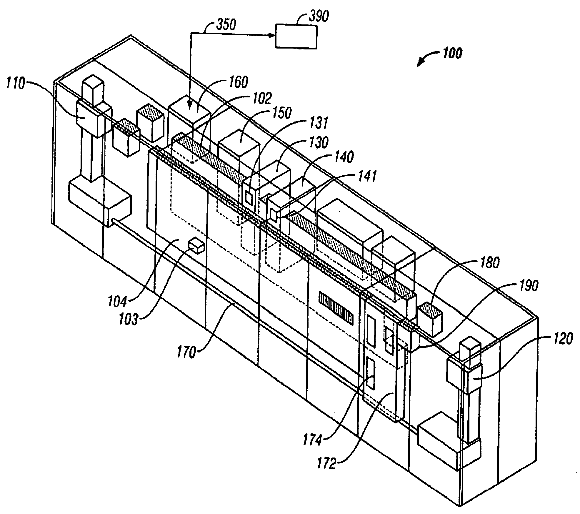
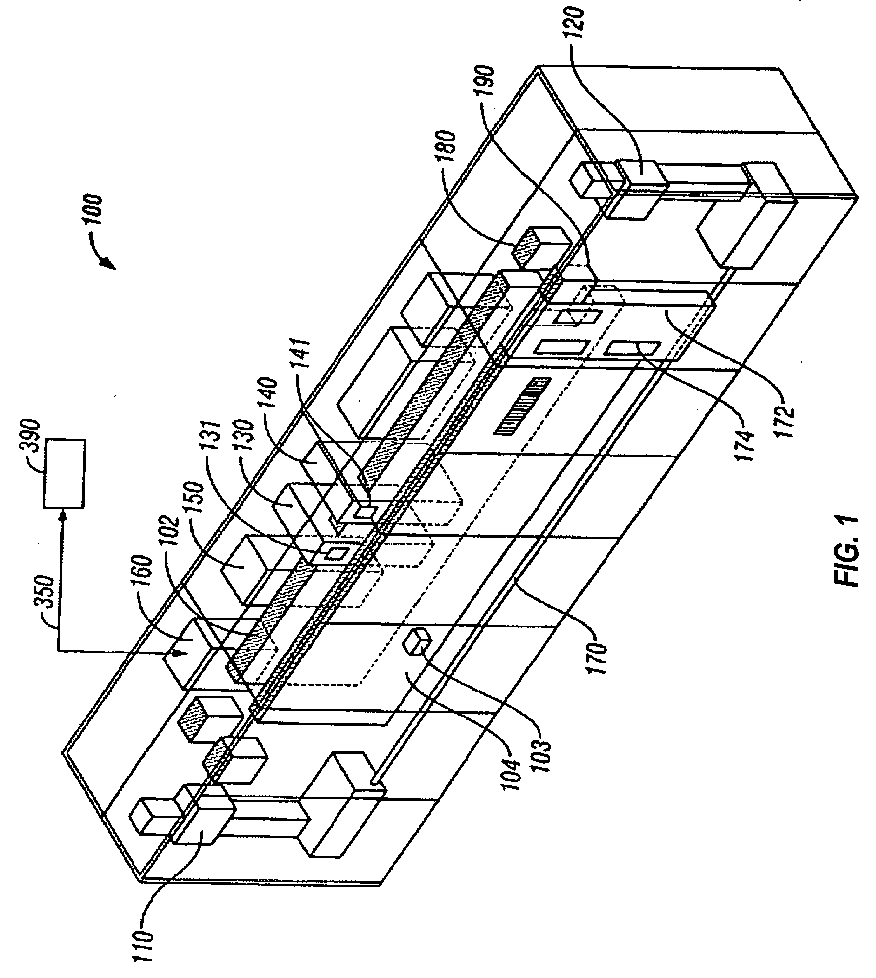
[0037] Referring to FIG. 1, a data storage and retrieval system 100 is shown. In the embodiment illustrated, data storage and retrieval system 100 is depicted as a robotic library. The upper interface of controller 160 allows data storage and retrieval system 100 to communicate with one or more hosts 390 via link 350. Link 350 may comprise an Ethernet, Infiniband, TCP / IP, Fibre Channel-Arbitrated Loop, SCSI, ESCON, FICON, or the like, depending on the application. The lower interface of controller 160 communicates with a plurality of drives that are positioned in drive enclosures 130 and 140. Drive enclosures 130 and 140 receive removable media cartridges 103 (e.g., see cartridges in FIGS. 3, 6, and...


PUM


Abstract

A cartridge storage device includes a housing having a front and a back. A plurality of cells are mounted in the housing, each cell adapted for receiving a media cartridge. A drive mechanism drives the cells towards a front opening in the front of the housing for allowing insertion and retrieval of the cartridges from the cells by the picker. Optionally, the back of the housing can have a rear opening for allowing in situ user-insertion and retrieval of the cartridges from the cells as well as viewing of the cartridges.

Description

FIELD OF THE INVENTION [0001] The present invention relates to media cartridge storage devices, and more particularly, this invention relates to a modular multi-cartridge storage device. BACKGROUND OF THE INVENTION [0002] Data storage drives, such as data tape drives, record information to and read information from media, such as the data tape of a tape cartridge. Data storage drives are often used in conjunction with, for example, a data storage and retrieval system. One example of such a system is an automated data storage library with robotic picking devices, wherein removable media cartridges are selectively transported between storage cells and data storage drives in an automated environment. Herein, automated data storage library, data storage library, tape library system, data storage and retrieval system, and library may all be used interchangeably. [0003] Once requested, data that is stored on data storage media of an automated data storage library typically is needed quick...

Claims


Application Information

Patent Timeline
IPC IPC(8): G11B15/68
CPCG11B15/6835G11B23/0236G11B15/6885
Inventor MCINTOSH, MICHAEL PHILIPNAVE, SHAWN MICHAEL
Owner IBM CORP
Why Eureka
Try Eureka