
Coaxial reflectometer sensor elements

a technology of reflectometer and sensor element, applied in the direction of well-logging, electrical/magnetic detection, survey, etc., can solve the problems of resistivity measurement ambiguity however tending to diminish, signal adverse influence, and techniques that have not been popularized by logging engineers and analysts, and achieve the effect of attenuating unwanted reflections

Active Publication Date: 2020-10-13
REEVES WIRELINE TECH
View PDF8 Cites 0 Cited by
  • Summary
  • Abstract
  • Description
  • Claims
  • Application Information

AI Technical Summary

Benefits of technology

The sensor element enhances the depth of investigation and reduces noise interference, providing more accurate and reliable dielectric constant measurements of rock properties, even in challenging downhole conditions.

Problems solved by technology

As is well known, prospecting for minerals of commercial or other value (including but not limited to hydrocarbons in liquid or gaseous form; water e.g. in aquifers; and various solids used e.g. as fuels, ores or in manufacturing) and assessing rock properties as aforesaid are economically and technically important and challenging activities.
This is particularly the case when the water in the formation is of low or zero salinity, the problems of resistivity measurement ambiguity however tending to diminish with increasing salinity of any water in the pores of the rock.
However, such techniques hitherto have not proved popular among logging engineers and analysts.
Moreover, such signals can be adversely influenced by non-rock features such as layers of mudcake, the nature of which is known to those of skill in the art.
As a result, the signals generated by emitter-receiver logging tools intended to measure permittivity tend to contain little information about the geology, etc., of the rock.
In consequence many rock permittivity measuring devices often are only used in laboratory environments to which rock samples are conveyed after their removal from a borehole.
Even in prior art permittivity-measuring logging tools that can be used in downhole environments the useful information in the signals often is dominated by noise, unwanted harmonics of desired signals, the effects of direct transmission paths not passing through the rock, reflections and so on.
In this regard the receiver elements normally are antennae that are tuned to resonate at frequencies typical of the transmitted energy and therefore are prone to the indicated drawbacks.

Method used


Image

  • Coaxial reflectometer sensor elements
  • Coaxial reflectometer sensor elements
  • Coaxial reflectometer sensor elements

Examples


Embodiment Construction

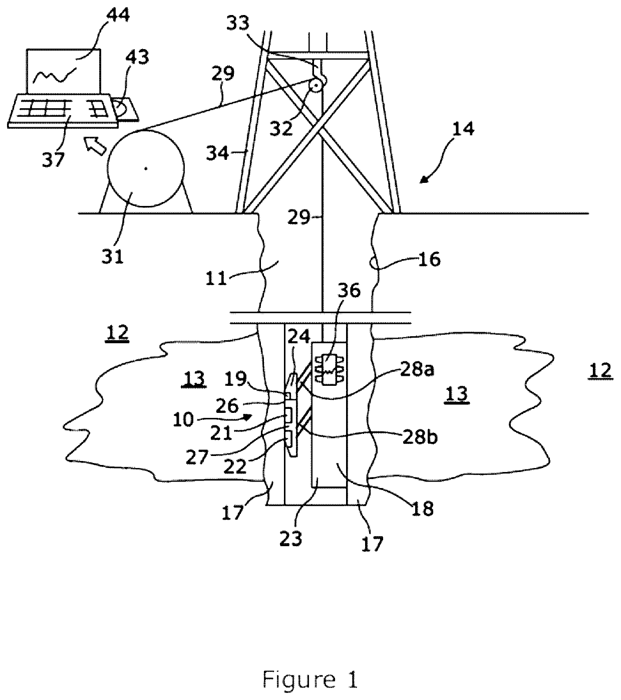
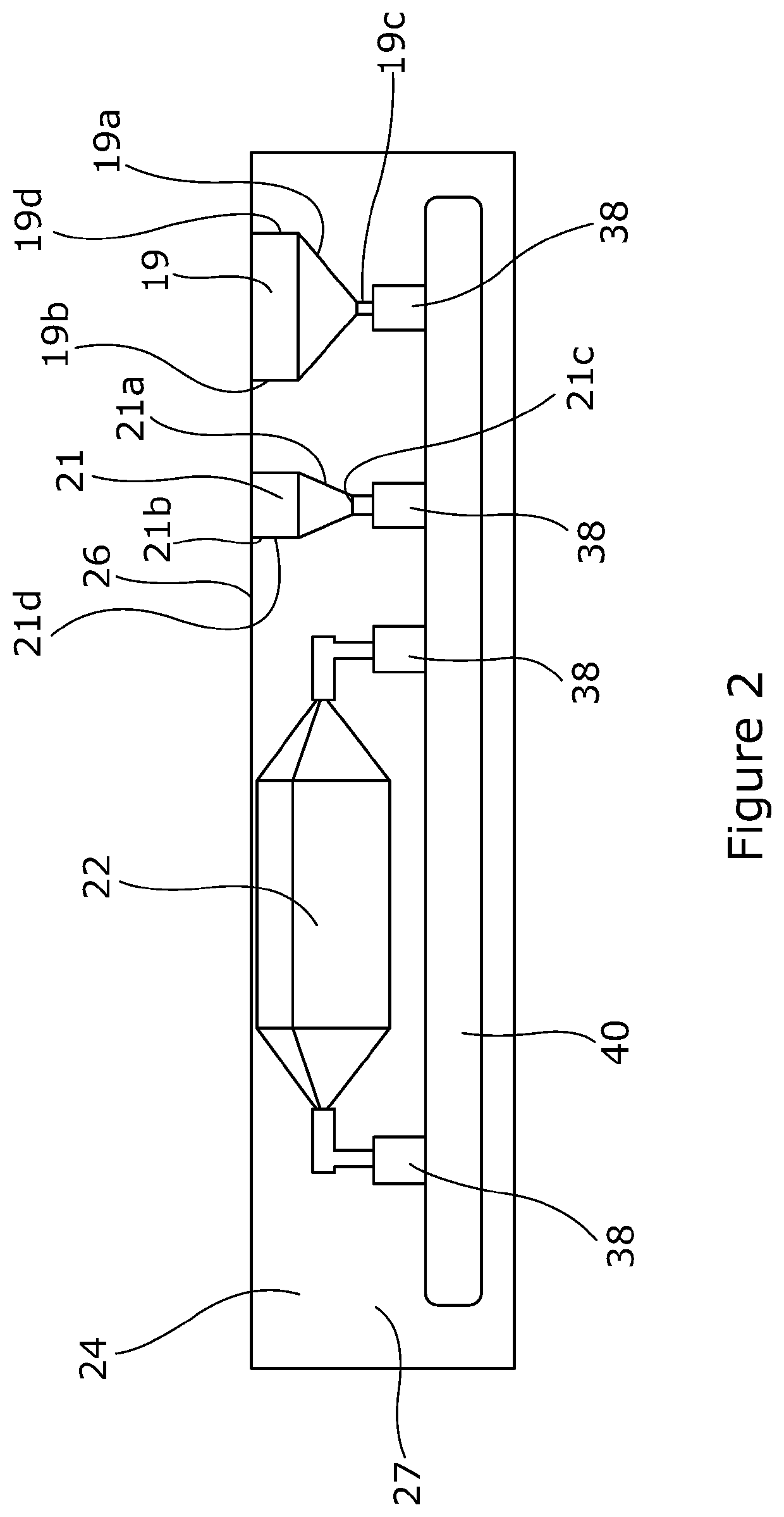
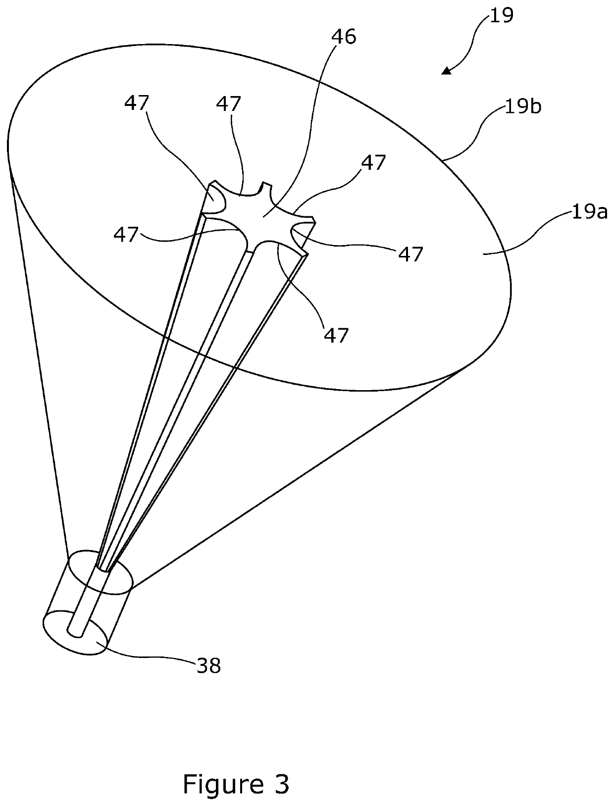
[0038]Referring to the figures apparatus 10 for determining the values of properties of layers of or associated with a borehole 11, and a borehole system incorporating such apparatus 10, are illustrated. The borehole 11 is shown extending through part of the Earth's crust in a manner that is familiar to those of skill in logging and related disciplines.

[0039]The borehole 11 is formed in rock 12 e.g. by drilling and may extend for hundreds or thousands of metres or feet, as indicated schematically in FIG. 1. The aim of creating the borehole 11 in the illustrated embodiment is to penetrate a schematically illustrated formation 13 that contains e.g. within pores in the rock 12 a fluid, or mixture of fluids, of interest as exemplified herein. The borehole may have as its primary purpose the exploration of the formation 13 or the extraction of fluid(s) of interest to an uphole, surface location 14. Boreholes such as borehole 11 also may be created and logged for other purposes. Non-limit...


PUM


Abstract

A reflectometer sensor element comprises (i) a recess formed in an electrically conducting material, the electrically conducting material defining a connection portion; the recess including an open end at or adjacent a surface of the electrically conducting material; and a transverse cross-sectional area defined by at least one wall of the recess increasing in at least a first region between the connection portion and the open end; (ii) an electrically conducting electrode that is spaced from the said at least one wall of the recess and extends between the open end and a location proximate the connection portion; and (iii) one or more dielectric materials occupying at least part of the recess between the at least one wall of the recess and the electrically conducting electrode. Such an element allows the detection of signals reflected from deeper within subterranean rock than has previously been possible.

Description

FIELD OF THE DISCLOSURE[0001]The subject matter of the present disclosure concerns improvements in or relating to coaxial reflectometer sensor elements.[0002]Such elements are useful inter alia in downhole logging operations in the determination of the relative permittivity or dielectric constant of rock.[0003]Logging techniques are used extensively in the mining and oil / gas industries to help locate formations containing various substances. Logging is also used when prospecting for e.g. underground water or when assessing features that may affect the stability, strength, hardness, porosity, or other parameters of rock. Such assessments are beneficial when preparing to recover hydrocarbons, water, and minerals, or when preparing for tunnelling or construction work. The last-mentioned may relate to the creation of above-ground or subterranean structures the latter including but not being limited to underground storage facilities.[0004]The subject matter of the present disclosure is o...

Claims


Application Information

Patent Timeline
Patent Type & Authority Patents(United States)
IPC IPC(8): G01V3/30G01V3/34E21B47/13E21B47/113
CPCG01V3/34G01V3/30E21B47/13E21B47/113G01V3/18G01V3/12G01V3/20G01V3/26G01R27/2617E21B47/00
Inventor CHANEY, DARREN
Owner REEVES WIRELINE TECH
Learn More