
Digital image processing with inherent compression

a digital image and compression technology, applied in the field of digital image processing with inherent compression, can solve the problems of inability to erase ink or toner deposited on paper, cost of cpu time, and complex green rectangle partially obscured by a red circle, so as to achieve greater speed, improve performance, and reduce the effect of resources consumed

Inactive Publication Date: 2006-07-06
ZENOGRAPHICS
View PDF83 Cites 16 Cited by
  • Summary
  • Abstract
  • Description
  • Claims
  • Application Information

AI Technical Summary

Benefits of technology

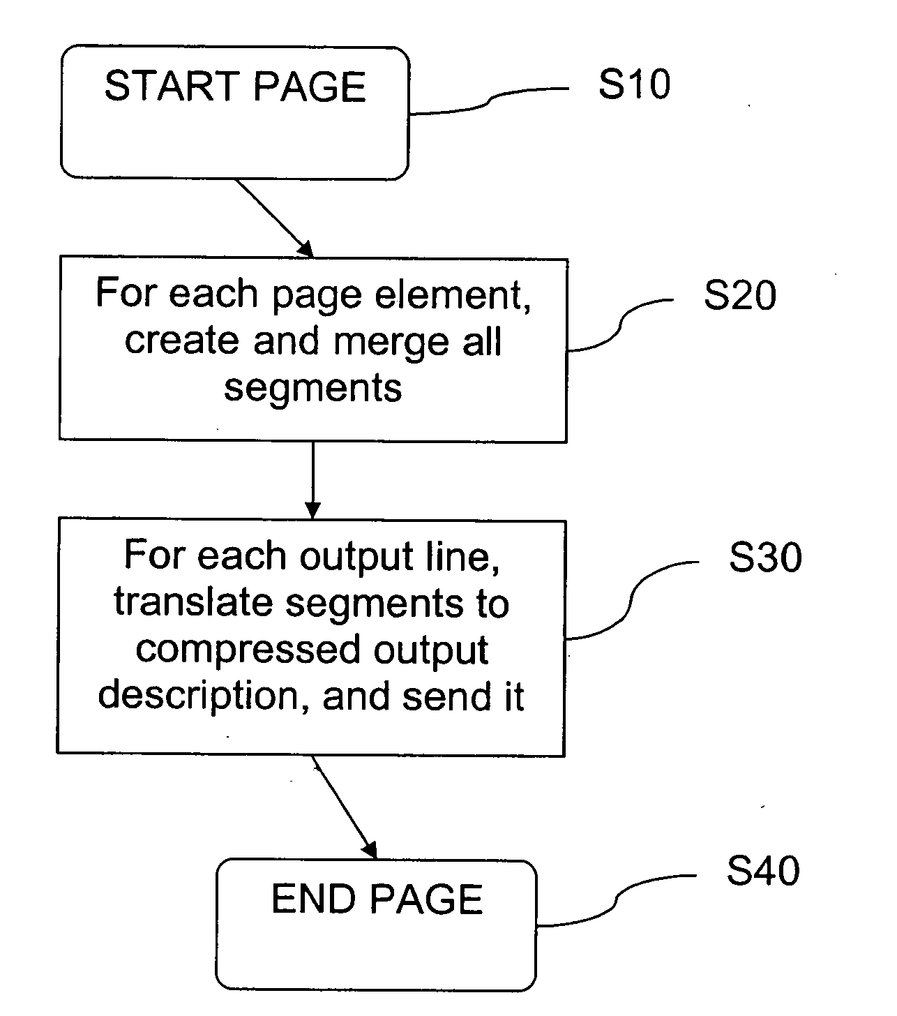
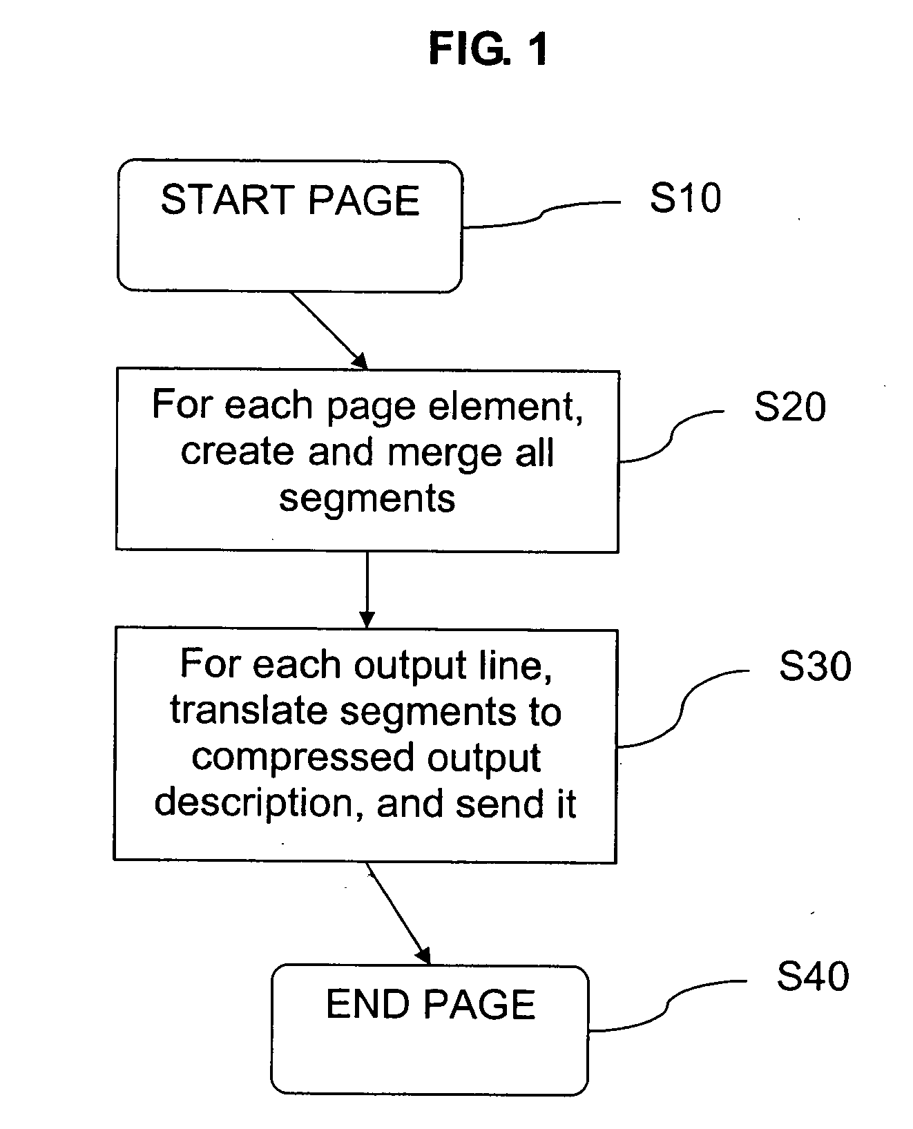
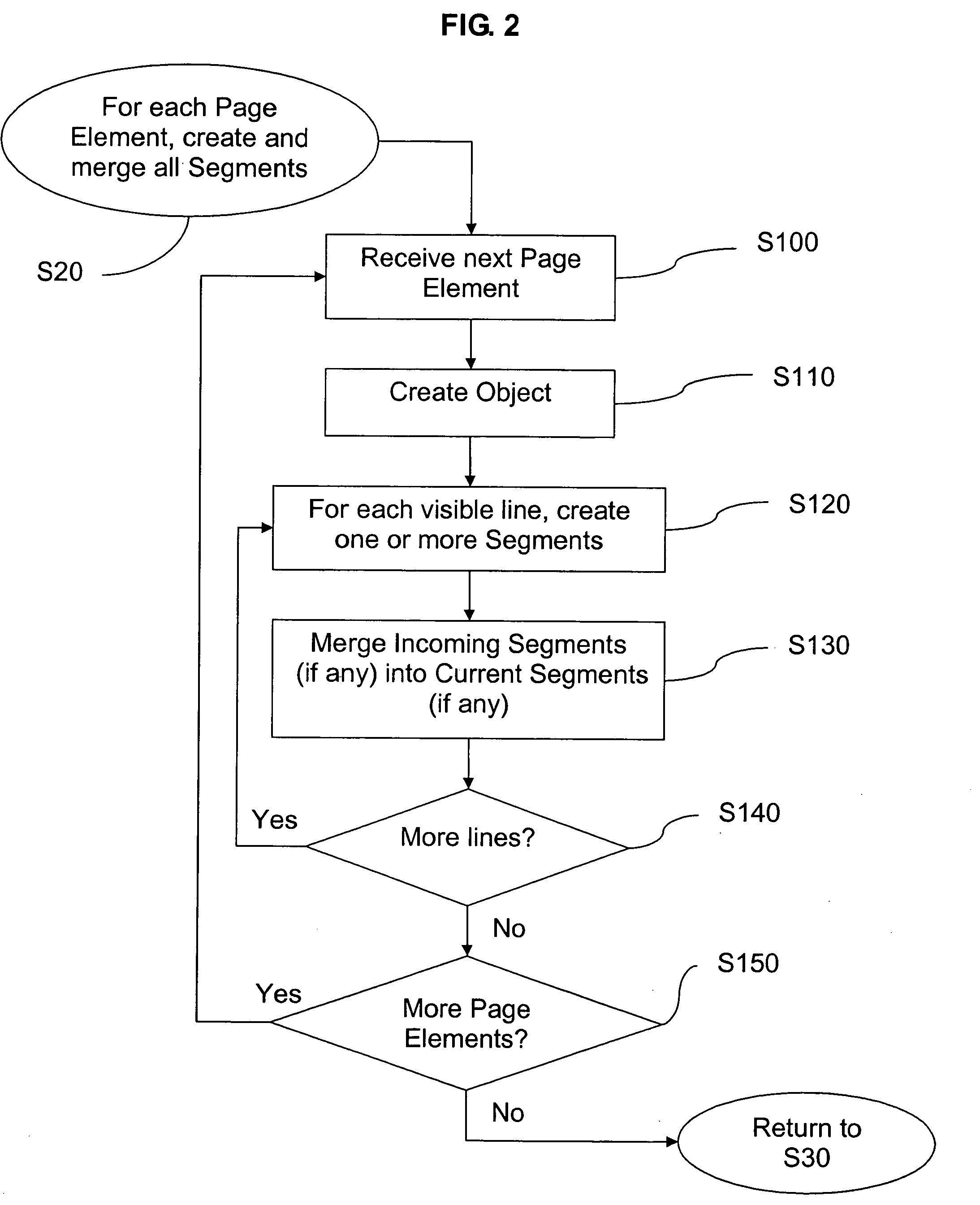
[0037] In an embodiment, a raster image processing system and method accepts a digital page description as a series of page elements (text, graphics, images, etc.) and creates output video-ready (“flattened”) raster without allocating large amounts of raster memory (arrays of pixels) and without creating a display list of all page elements. This technique dramatically improves performance (greater speed with fewer resources consumed) in the typical output process: rendering, image processing, compression, and transmission. The method records each page element in memory in a manner that largely retains the inherent compression of the element description, and fully retains the positional relationships with its neighboring elements. Where an incoming page element overlaps an existing one, the intersections are calculated on the fly, and elements underneath are split, merged, shrunken, or deleted. Each incoming page element is processed and recorded as described above, and then discarded. The result is a simple, non-overlapping (“flat”) representation of the final output raster. In other words, in one embodiment, the representation starts empty, then stays compressed and flat throughout while accumulating representations of page elements.

Problems solved by technology

Because these video output circuits are so simple, the combination of a quite general page element (at the level of the generating software) such as a green-filled rectangle partially obscured by a red circle is far too complex to be handled in real time during actual display or output.
Ink or toner deposited on paper cannot be erased.
There is only the cost of CPU time.
The link to the rasterizing problem is this: because the page elements can appear randomly, the rasterizer puts the elements' pixels into the RAM as it receives them, and there is potential for cache “thrashing”.
So, one big performance problem with conventional rasterizers is that they consume too much slow RAM.
But this problem is just the beginning.
The bulk of the frame buffer causes further big problems “downstream” since this huge amount of raster data must be both processed and then delivered eventually to the simple print engine video circuits.
The second big problem, derived from the first, is that in high-quality print systems further image-processing steps are required (color matching, trapping, halftoning, etc.).
If some of these operations are neighborhood operations (which examine and adjust each pixel in the context of its immediate neighbors), the CPU cost can be enormous: many times longer than the rasterization process itself.
A third big problem then arises from the bulky “raw” raster.
(Printers connected via Ethernet have widely varying bandwidth, but sometimes perform even worse than USB.)
And, a laser printer would need an equivalent and expensive amount of RAM to store the entire frame buffer since once the laser engine starts it cannot stop, and any delay in the arrival of the data after engine start would mean an incomplete print.
Since the printer's manufacturer would be unable to sell such a slow and expensive printer, the conventional solution to this problem is compression of the raster.
But, as is well known in the art, there is a fundamental trade-off with compression methods: the greater the compression, the greater the CPU time cost.
So, with these very large raster frame buffers, to effectively compress the data often takes more CPU time than to rasterize in the first place.
Further straining this bloated, inefficient, slow system is a optional quality requirement that each page element be handled differently by class of element.
Another problem immediately presents itself: this odd number is awkward for modern computers.
These two separate arrays now are even more likely to “thrash” the cache.
A final, fatal blow to the conventional rasterizer is an even higher quality requirement on color pixel precision.
None solve the original problem without introducing new major problems.
Second, elements that span more than one band must be processed more than once.
The display list problem is small for simple pages.
But for complex pages, the display list storage problem is crippling or fatal.
Upon overflow, some of the prior art attempts to “fallback” to raw raster at a lower quality, but the fundamental problem remains: there will be pages that either outright fail to print, or at least fail to print at the normal quality level.
The second performance problem with banding, though less severe, may still impair performance dramatically.
Generating then discarding that raster data wastes CPU time.
While it is sometimes possible to “clip” the element cleanly at band boundaries, often this is not entirely precise and is inefficient again due to wasted results.
While this can cut down on redundant pixel drawing, it retains the problem of display list overflow, and adds the problem of object sorting.
This method retains the display list overflow problem, and adds the problem of potentially huge active object and active runs lists.

Method used


Image

  • Digital image processing with inherent compression
  • Digital image processing with inherent compression
  • Digital image processing with inherent compression

Examples


Embodiment Construction

[0084] Certain embodiments of this invention flatten incoming page elements while largely retaining their inherent compression. The following table explains the concept of inherent compression for each page element class.

PageElementClassSpecificationInherent CompressionExampleTextSpecified as anUnique characters per“This is a test” has 7array of [(x, y)font / size are stored run-unique letters (“T”, “h”,position, glyphlength compressed in a“i”, “s”, “a”, “t”, “e”), withID]document glyph cache.each glyph run-lengthcompressed (18 pt yields3:1 or better).GraphicsSpecified asThe array of verticesA rectangle with corners atobject typeconsumes just 2 integers(100, 100) and (500, 500) is(rectangle, line,per vertex (8 bytes eachspecified with just twopolygon, etc.)on a 32-bit CPU)vertices, compared to awith two or moreraster area of 400 × 400 = 160,000(x, y) vertices.pixels.ImagesSpecified as aFor printing, typically theA 3″× 4″ photo from a websource image, andsource image is lower-page ar...


PUM


Abstract

A raster image processing system and method accepts a digital page description as a series of page elements (text, graphics, images, etc.) and creates output video-ready (“flattened”) raster without allocating large amounts of raster memory (arrays of pixels) and without creating a display list of all page elements. This technique improves performance (greater speed with fewer resources consumed) in the typical output process: rendering, image processing, compression, and transmission. The method records each page element in memory in a manner that largely retains the inherent compression of the element description, and fully retains the positional relationships with its neighboring elements. Where an incoming page element overlaps an existing one, the intersections are calculated on the fly, and elements underneath are immediately split, merged, shrunken, or deleted. Each incoming page element is immediately processed and recorded as described above, and then discarded. The result is a continuously precise, simple, non-overlapping (“flat”) representation of the final output raster. In other words, in one embodiment, the representation starts empty, then stays compressed and flat throughout while accumulating representations of page elements.

Description

PRIORITY APPLICATION [0001] This application claims priority under 35 U.S.C. §119(e) from U.S. Provisional Patent Application Ser. No. 60 / 641,682, entitled “Digital Image Processing Without Rasterization” and filed Jan. 6, 2005, the entirety of this is hereby incorporated by reference.BACKGROUND OF THE INVENTION [0002] 1. Field of the Invention [0003] This invention relates generally to methods and systems for rendering computer-generated page descriptions into raster pixel arrays for use in digital output systems such as printers. [0004] 2. Description of the Related Art [0005] Output systems for digital images include computer displays (“monitors”) and printers. Users of computer software such as word processors, drawing programs, and spreadsheets create documents that place text, graphics, and bitmaps (e.g. photographs) on one or more pages of a document. Other sources of digital page descriptions are the World Wide Web (notably HTML pages), and computer software (e.g. database s...

Claims


Application Information

Patent Timeline
IPC IPC(8): G06F3/12
CPCG06F3/1206G06F3/1243G06F3/1244G06F3/1284
Inventor ROMNEY, ROBERT E.
Owner ZENOGRAPHICS
Learn More