Heat dissipating device

a heat dissipation device and heat dissipation fin technology, which is applied in the direction of cooling/ventilation/heating modification, semiconductor device details, semiconductor/solid-state device details, etc., can solve the problems of adversely affecting the operation stability of computer electronic devices, large heat generation of computer electronic devices such as central processing units (cpus), and limited heat dissipation surface area, etc., to achieve satisfactory heat dissipation

Inactive Publication Date: 2006-07-06
HON HAI PRECISION IND CO LTD +1
View PDF5 Cites 38 Cited by
  • Summary
  • Abstract
  • Description
  • Claims
  • Application Information

AI Technical Summary

Benefits of technology

[0008] Accordingly, what is needed a heat dissipating device which removes heat fr

Problems solved by technology

Computer electronic devices such as central processing units (CPUs) generate lots of heat during normal operation.
If not properly removed, such heat can adversely affect the operational stability of the computer electronic devices.
However, the aluminum extrusion heat sinks, which each commonly include a flat base and a plurality of fins extending upwardly from the base, have many drawbacks.
The first drawback is that the total surface area of the fins available for heat dissipation is very limited as the made space between adjacent fins cannot be desirably small enough.
This drawback seriously bars improvement of the heat removal rate of the aluminum extrusion heat sinks.
Another drawback is th

Method used


Image

  • Heat dissipating device
  • Heat dissipating device
  • Heat dissipating device

Examples


Embodiment Construction

[0014] Reference will now be made to the drawing figures to describe a heat dissipating device 1 of a preferred embodiment in accordance with the present invention in detail.

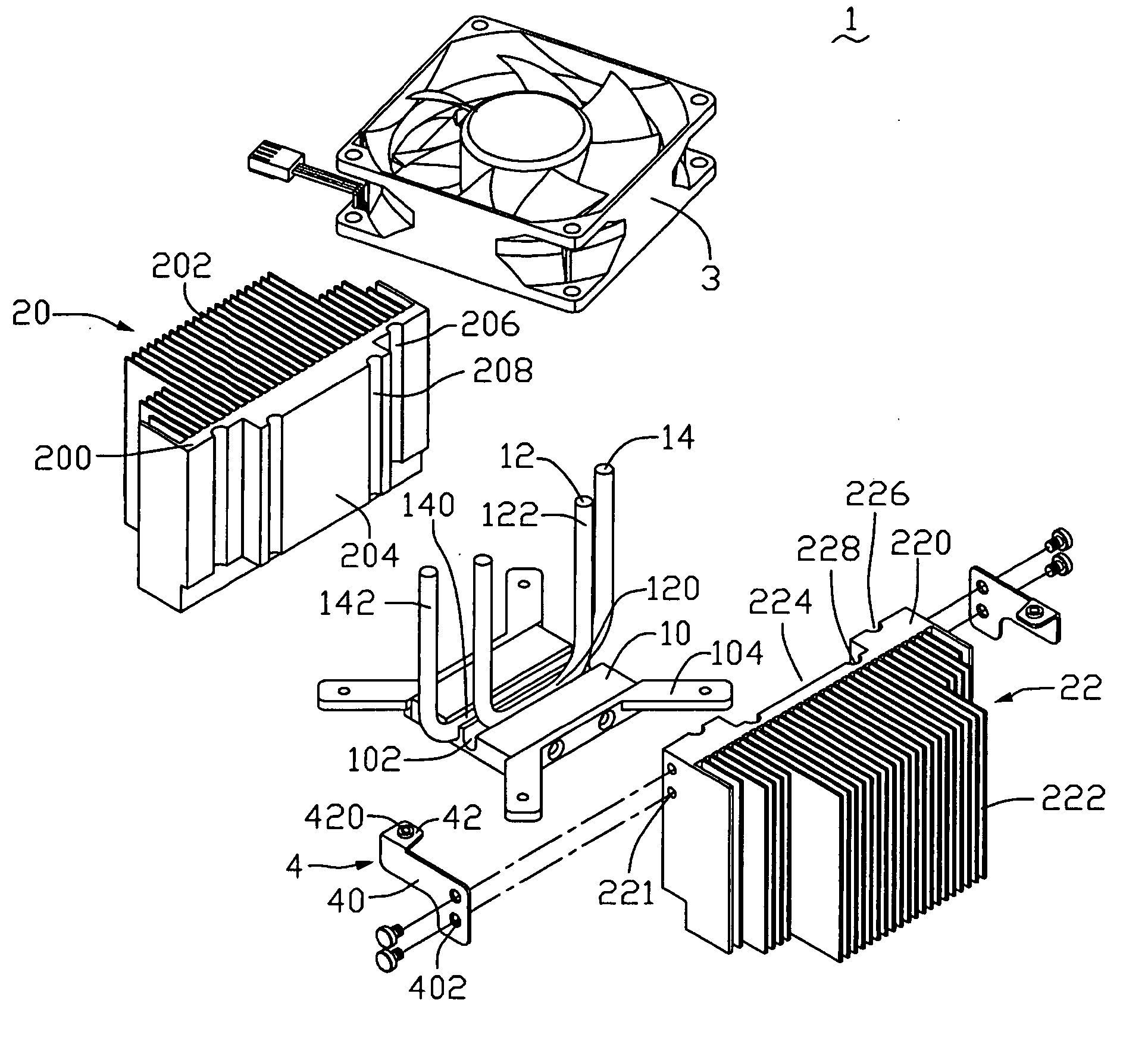
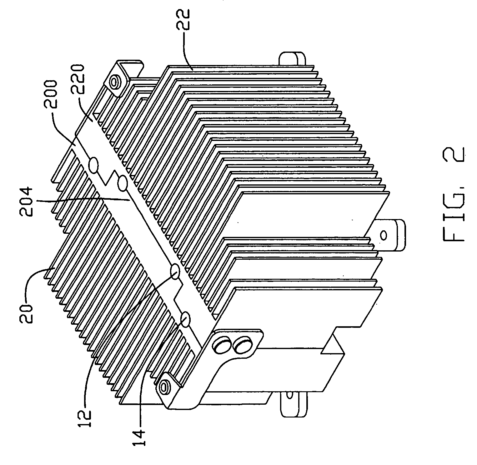
[0015] Referring FIG. 1 to FIG. 3, the heat dissipating device 1 comprises a heat spreader 10, a pair of U-shaped pipes 12, 14, a radiator 2, a fan 3 for mounting on the radiator 2 and a pair of clips 4.

[0016] The heat spreader 10 is preferably made of copper or aluminum material and has a bottom mating surface. The mating surface is adapted for contacting a heat source such as a CPU (not shown). The heat spreader 10 defines a pair of parallel grooves 102 in a top surface thereof, opposing the mating surface. The heat spreader 10 forms ears 104 extending outwardly at each corner thereof. The heat spreader 10 is fastened on the CPU by extending screws or bolts through the ears 104 to engage a retainer surrounding the CPU. The CPU and the retainer are not shown in the drawings.

[0017] The heat pipe 12 comprises ...


PUM


Abstract

A heat dissipating device (1) includes a heat spreader (10), a radiator (2), at least one U-shaped heat pipe (12), a fan (3) mounted on the radiator and a pair of clips (4). The radiator includes a first heat sink (20) and a second heat sink (22). The first heat sink (20) includes a first base (200) and a plurality of fins (202) extending from a side of the first base. The second heat sink (22) includes a second base (220) and a plurality of fins (222) extending from a side of the second base. The heat pipe (12) includes an evaporating portion (120) attached to the heat spreader and a pair of condensing portions (122) extending upwardly from opposite ends of the evaporating portion. The two condensing portions are sandwiched between the first base and the second base. The heat pipe transfers heat from the heat spreader to both of the first base and second base.

Description

BACKGROUND [0001] 1. Field [0002] The present invention relates generally to heat dissipating devices for removing heat from heat-generating devices, and more particularly to a heat dissipating device having great heat dissipation efficiency for cooling electronic devices such as Central Processing Units (CPUs). [0003] 2. Prior Art [0004] Computer electronic devices such as central processing units (CPUs) generate lots of heat during normal operation. If not properly removed, such heat can adversely affect the operational stability of the computer electronic devices. Solutions must be taken to efficiently remove the heat from the CPUs. Typically, a heat sink is mounted on a CPU to remove the heat therefrom. [0005] Conventional heat sinks such as aluminum extrusion type heat sinks are widely used for heat dissipation of electronic devices. However, the aluminum extrusion heat sinks, which each commonly include a flat base and a plurality of fins extending upwardly from the base, have...

Claims


Application Information

Patent Timeline
IPC IPC(8): H05K7/20
CPCH01L23/427H01L23/467H01L2924/0002H01L2924/00F28D15/0275
Inventor YU, GUANG YULEE, HSIEH-KUN LEELU, CUI-JUN LU
Owner HON HAI PRECISION IND CO LTD
Why Eureka
Try Eureka