
Controlled flow of source material via droplet evaporation

a droplet evaporation and source material technology, applied in vacuum evaporation coatings, chemical vapor deposition coatings, coatings, etc., can solve the problems of difficult to transport the material in gaseous form, difficult to achieve the type and composition of the layers that can be formed using cvd, and difficult to achieve the effect of gaseous transpor

Inactive Publication Date: 2006-07-06
ADVANCED TECH MATERIALS INC
View PDF10 Cites 13 Cited by
  • Summary
  • Abstract
  • Description
  • Claims
  • Application Information

AI Technical Summary

Benefits of technology

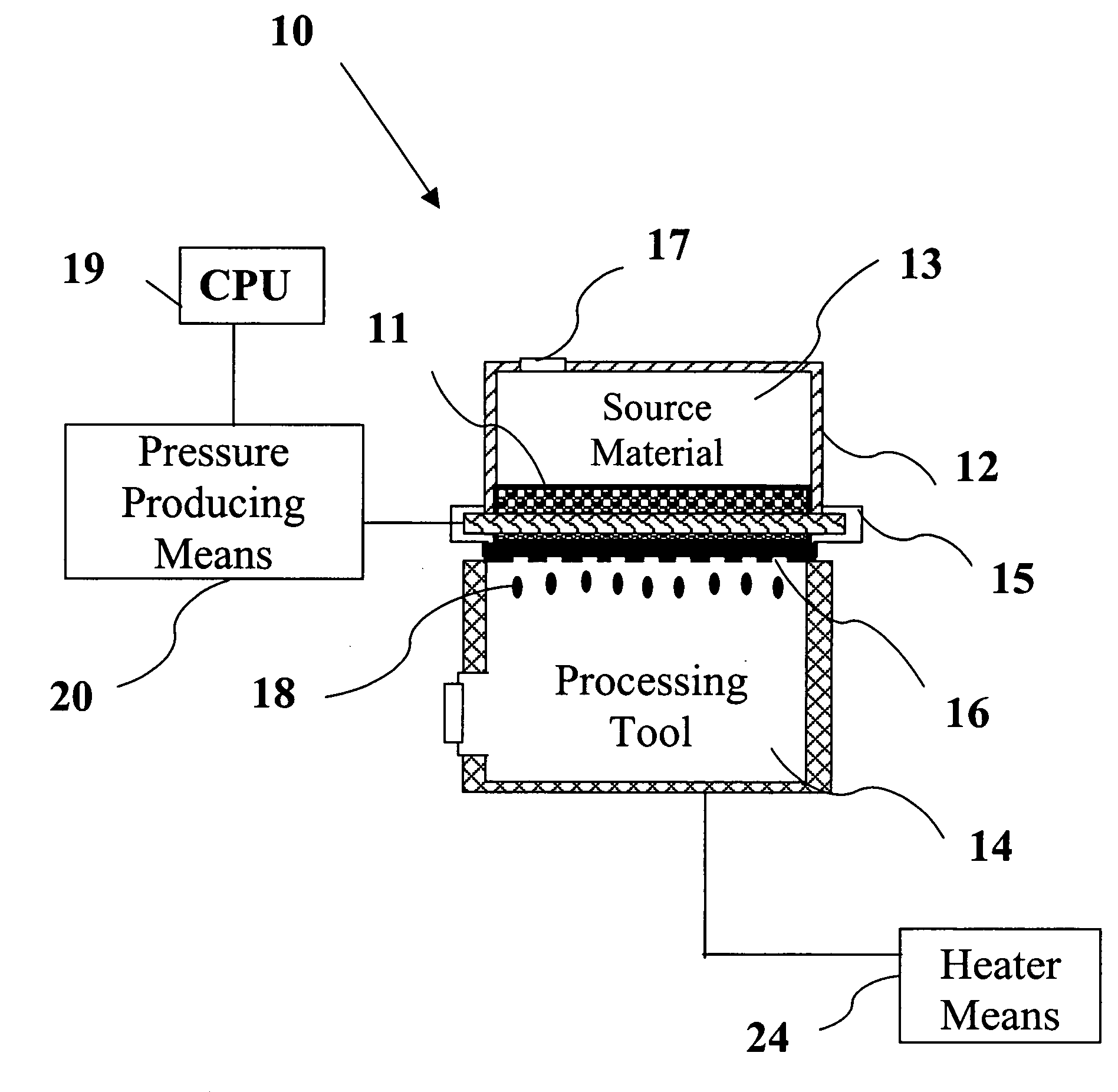
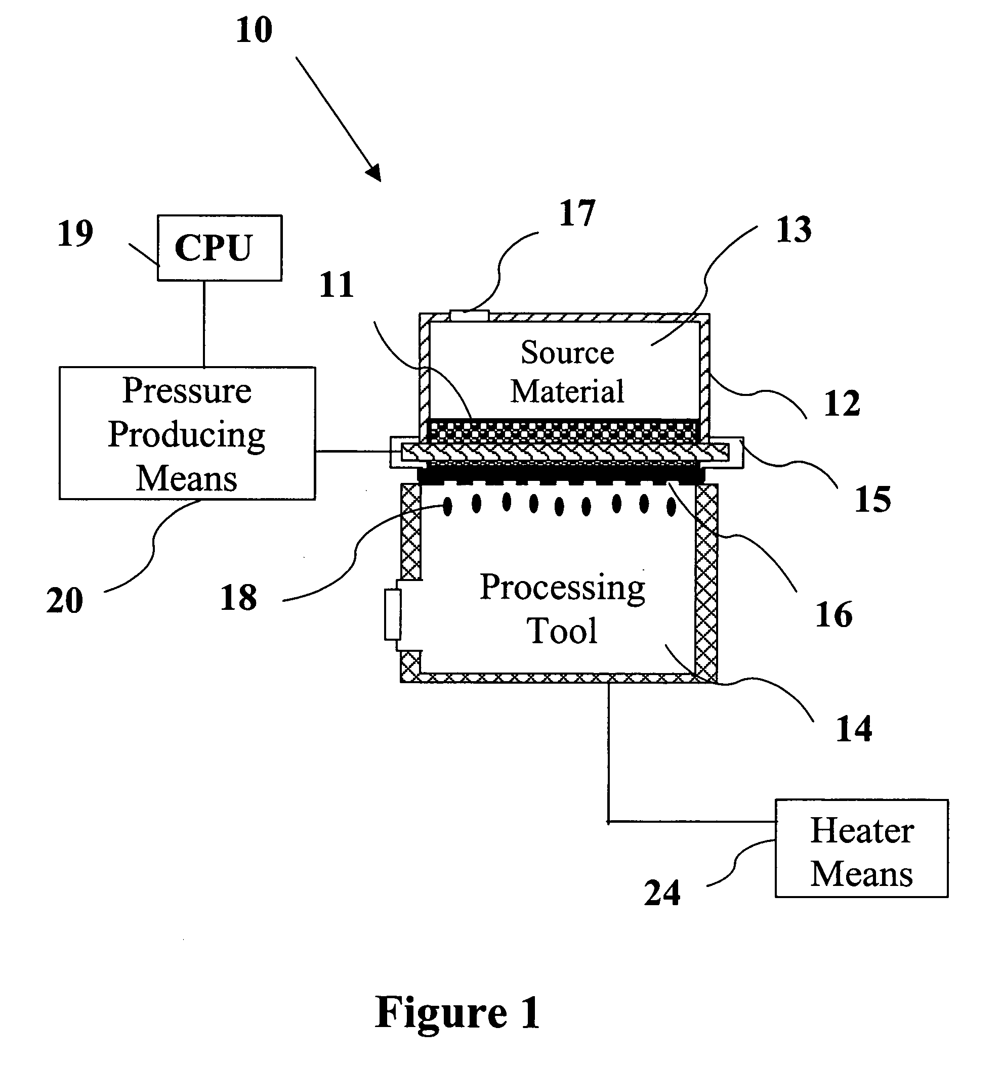
[0030] applying sufficient pressure by mechanical and / or thermal means, to the liquefied source material to increase pressure therewithin in a sufficient amount to eject the liquefied source material through a plurality of nozzles thereby generating droplets of the liquefied source material for introduction into the downstream processing tool or source / vaporization chamber.
[0031] Other aspects and features of the invention will be more fully apparent from the ensuing disclosure and appended claims.

Problems solved by technology

The type and composition of the layers that can be formed using CVD is limited by the ability to deliver the reactants or reactant precursors to the surface of the substrate.
However, this procedure has proven to be problematic because of the inability to deliver, at a controlled rate, a reproducible flow of vaporizable precursor to the vaporizer.
However, decaborane is a low vapor pressure solid at room temperature, and as such, it is difficult to transport the material in a gaseous form at the flow rates required by the ion implant tool.
Notably, difficulties still arise when attempting to control the flow rate.
This often increases the size of the MFC, which is not the optimal way to control the flow.
Further, even if the decaborane makes it through the MFC, it can readily condense further downstream if a cold spot is encountered.
Thus, these issues make it difficult to achieve a steady flow rate, thereby causing poor yield or quality at the wafer.

Method used


Image

  • Controlled flow of source material via droplet evaporation
  • Controlled flow of source material via droplet evaporation
  • Controlled flow of source material via droplet evaporation

Examples


example 1

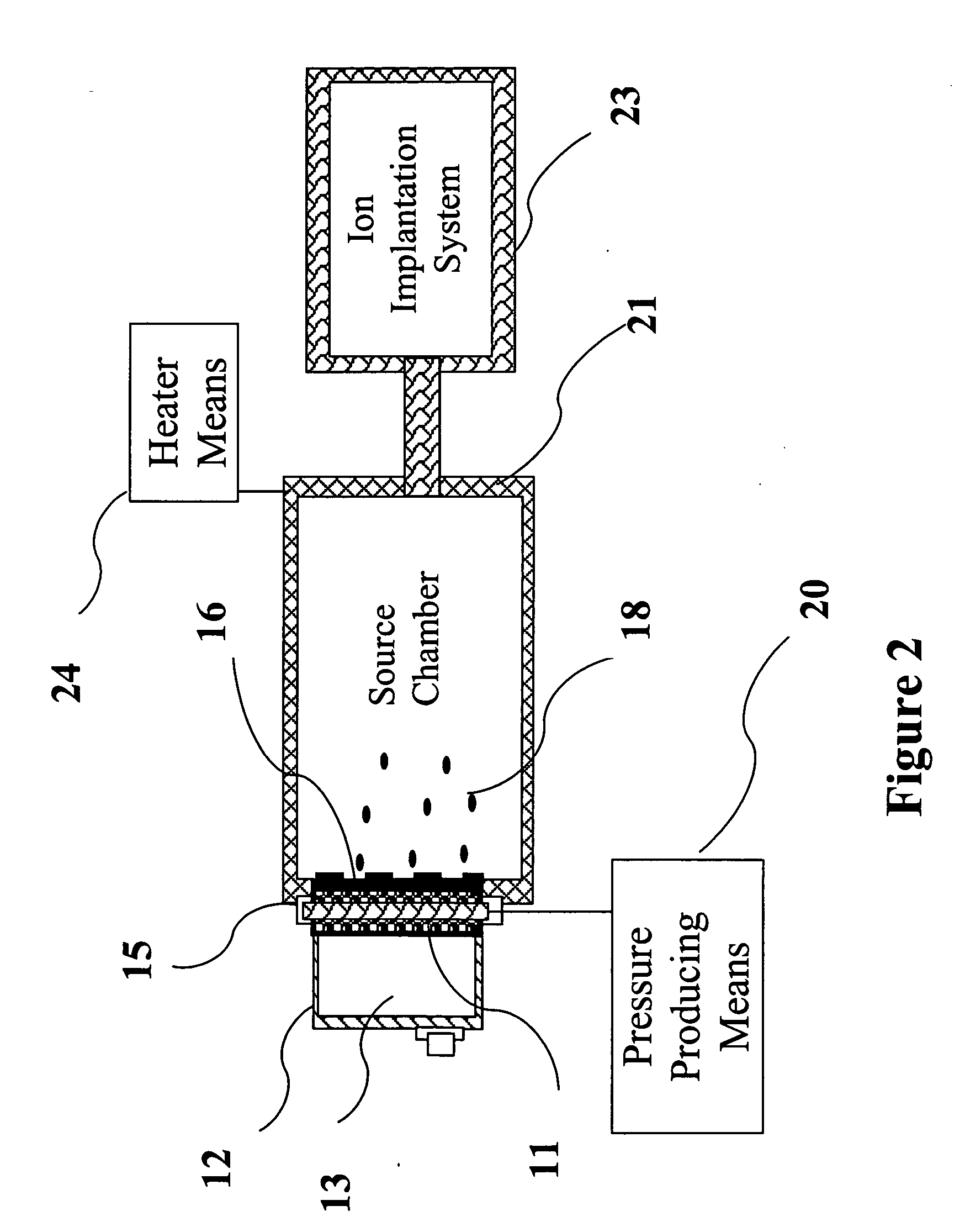
[0059] A system such as described in FIG. 1 is used to produce vaporized decaborane for use in an ion implantation system. In operation, the delivery system of the present invention introduces solid decaborane into the source material vessel, which is placed directly over a source chamber in an ion implantation system. Because the temperature required to melt decaborane (100° C.) will accelerate its decomposition, only the bottom surface of the solid decaborane will be heated. Thus, the heating means will be positioned beneath the solid source material. The heat will cause the bottom surface of the solid source material to melt and drip into the nozzle area. Heating preferably is accomplished by a vertical support piece comprising a resistive heating device. Further, to ensure consistent temperature during the droplet generation and ejection, the nozzle plate comprising a plurality of nozzles may be heated.

[0060] The quantity of nozzles is preferably between 600 to 1000 wherein eac...


PUM

PropertyMeasurementUnit
aperture bore diameteraaaaaaaaaa
diameteraaaaaaaaaa
diameteraaaaaaaaaa

Abstract

A system for delivering a controlled and stable flow of vaporizable source material for use in semiconductor manufacturing applications. The system includes a droplet generator, which includes a plurality of nozzles and a pressure producing means. When sufficient pressure is applied to a liquefied or liquefiable source material, droplets of the source material are generated and ejected from the nozzles into a downstream processing tool or source / vaporization chamber. The pressure is applied either through the use of a heating element or an electromechanical transducer.

Description

BACKGROUND OF INVENTION [0001] 1. Field of the Invention [0002] The present invention relates to a delivery system, and more particularly, to a system for delivering a controlled and reproducible flow of vaporizable source material for use in chemical vapor deposition (CVD), ion implantation and other semiconductor manufacturing process systems. [0003] 2. Description of Related Art [0004] Chemical vapor deposition has been extensively used for preparation of films and coatings in semiconductor wafer processing. CVD is a favored deposition process in many respects, for example, because of its ability to provide highly conformal and high quality films, at relatively fast processing times. Further, CVD is beneficial in coating substrates of irregular shapes including the provision of highly conformal films even with respect to deep contacts and other openings. [0005] In general, CVD techniques involve the delivery of gaseous reactants to the surface of a substrate where chemical reacti...

Claims


Application Information

Patent Timeline
Patent Type & Authority Applications(United States)
IPC IPC(8): C23C16/00
CPCC23C14/48C23C16/4486
Inventor SWEENEY, JOSEPH D.ARNO, JOSE
Owner ADVANCED TECH MATERIALS INC
Learn More