Rear projection display

a projection display and rear projection technology, applied in the direction of projectors, color television details, instruments, etc., can solve the problems of not being able to achieve high luminance, not being able to render equal all the path lengths of color light, and being necessary to make a color separation of white light, etc., to achieve assembly or assembly accuracy.

Inactive Publication Date: 2006-06-29
SANYO ELECTRIC CO LTD
View PDF8 Cites 18 Cited by
  • Summary
  • Abstract
  • Description
  • Claims
  • Application Information

AI Technical Summary

Benefits of technology

[0004] In view of the above circumstances, it is an object of the present invention to provide a rear projection display, not requiring a dichroic prism and capable of rendering the generation system of each image light in color independent of the other generation systems so as to optimally construct, improve easiness of assembly of, and so on, each projection optical system.
[0006] In the above configuration, it is possible to be liberated from disadvantages and various constraints of a case of using the dichroic prism. In addition, it is possible for the plurality of optical systems for projecting image light in color to individually exist in such a manner that each of the plurality of optical systems for projecting image light in color includes the light source. Thus, it becomes easy to bring into a unit. For example, the light valve and the light source are rendered a unit, or the projection portion, the light valve, and the light source are rendered a unit. This increases easiness of assembly or accuracy of assembly. Furthermore, it becomes possible to individually construct or control the light sources depending on each optical system for projecting image light in color so that the rear projection display can optimally perform.
[0019] According to the present invention, it is possible to be liberated from disadvantages and various constraints of a case of using the dichroic prism. In addition, it is possible for the plurality of optical systems for projecting image light in color to individually exist in such a manner that each of the plurality of optical systems for projecting image light in color includes the light source. Thus, it becomes easy to bring into a unit. This increases easiness of assembly or accuracy of assembly. Furthermore, it becomes possible to individually construct or control the light sources depending on each optical system for projecting image light in color so that the rear projection display can optimally perform.

Problems solved by technology

Thus, there are various drawbacks that light in a certain wavelength band is cut, and because of this cutting, it is not possible to realize high luminance, and so forth.
On the other hand, in an art of the latter invention, there is a drawback that it is necessary to make a color separation of the white light from the one light source.
In addition, there is another drawback that in this color separation, it is not possible to render equal all the color light's path lengths from the light sources to the liquid crystal display panel.
Thus, it is not possible for the projection system of the image lights of respective colors to individually exist in such a manner that the projection system of the image lights of respective colors includes the particular light source (that is, not possible to become one assembly).
In addition, it is difficult to optimally construct or optimally control the light sources in each projection system of the image lights of respective colors.

Method used


Image

  • Rear projection display
  • Rear projection display
  • Rear projection display

Examples


Embodiment Construction

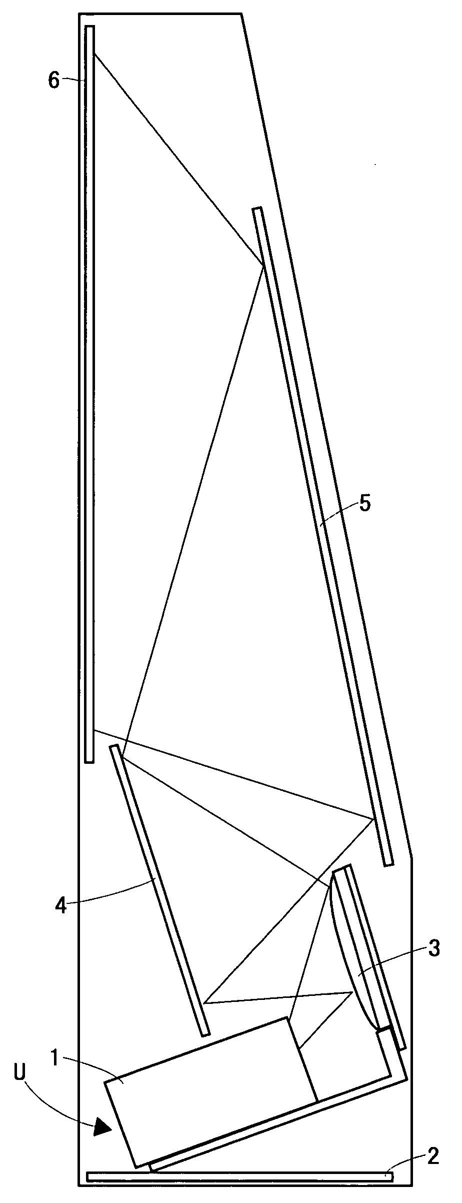
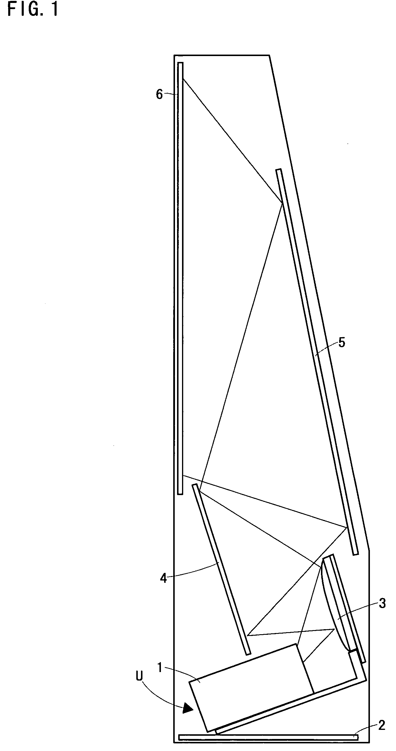
[0028] Hereinafter, a rear projection display of an embodiment of the present invention will be described based on FIG. 1 to 7.

[0029]FIG. 1 is a side view showing internal structure (optical system) of the rear projection display of this embodiment. At a lower structural portion of a chassis 2 of the rear projection display, a position adjustment mechanism (not shown) is provided, and on this position adjustment mechanism, an image-light generation optical unit U is mounted. The image-light generation optical unit U is formed of an optical system for generating image light 1 and three aspheric mirrors 3. Image lights of respective colors emitted from the optical system for generating image light 1 are reflected by each of the aspheric mirrors 3. Furthermore, at a position where the image lights of respective colors reflected by the aspheric mirrors 3 are received, a reflecting mirror 4 is placed. The reflecting mirror 4 is attached to the chassis 2 by an adjustment screw (not shown...


PUM


Abstract

A rear projection display, not requiring a dichroic prism, and capable of rendering a generation system of each image light in color independent of the other generation systems so as to optimally construct and improve easiness of assembly of, and so on, each generation system, is provided. Each unit for projecting image-light is formed of an LED array, a rod integrator, a liquid crystal display panel, and a projection lens. A projection optical axis of the projection lens of each unit for projecting image-light is parallel each other. A unit for projecting image light in red is provided with an LED array for emitting light of a wavelength band in red, a unit for projecting image light in green is provided with an LED array for emitting light of a wavelength band in green, and a unit for projecting image light in blue is provided with an LED array for emitting light of a wavelength band in blue. Each image light in color obtained as a result of passing through the liquid crystal display panel is projected by the projection lens, and displayed on a screen. As a result, each image light in color is superposed on the screen, and an image in full color is displayed.

Description

TECHNICAL FIELD [0001] The present invention relates to a rear projection display. BACKGROUND ART [0002] It has been proposed a projection type image display apparatus provided with light sources of three colors for respectively emitting three primary colors, optically modulating by light valves lights of respective colors from the light sources of respective colors, combining by a dichroic prism image lights of respective colors obtained as a result of this optical modulation, and projecting by a projection lens image light in full color obtained as a result of this combination (see Japanese Patent Laying-open No. 2004-220015, referred to as the former invention). In addition, it has been proposed a liquid crystal rear projection television, in which light of respective colors obtained as a result of separating white light from one light source are optically modulated by a liquid crystal display panel, image lights of respective colors obtained as a result of this optical modulatio...

Claims


Application Information

Patent Timeline
IPC IPC(8): G03B21/22
CPCG03B21/10G03B21/16G03B21/28H04N9/3105H04N9/3141H04N9/3197
Inventor IKEDA, TAKASHIMIWA, TAKASHIMURATA, HARUHIKOKANAYAMA, HIDEYUKI
Owner SANYO ELECTRIC CO LTD
Why Eureka
Try Eureka