
Vapour compression heat pump system

a heat pump and vacuum technology, applied in refrigeration components, mechanical equipment, light and heating equipment, etc., can solve the problems of inability to superheat the compressor suction gas, etc., to achieve different heating capacity, reduce high side pressure, and increase the temperature of the compressor

Inactive Publication Date: 2006-06-29
SINVENT AS
View PDF2 Cites 8 Cited by
  • Summary
  • Abstract
  • Description
  • Claims
  • Application Information

AI Technical Summary

Benefits of technology

[0009] A major object of the present invention is to make a simple, efficient system that avoids the aforementioned shortcomings and disadvantages.
[0012] The present invention is based on the system described above, comprising at least a compressor, a heat rejector, an expansion means and a heat absorber. By superheating the compressor suction gas temperature, the compressor exit temperature can be increased without increasing the exit pressure and hot water at desired temperatures can be produced. By using a split flow at appropriate temperature from the heat rejector, it is possible to superheat the compressor suction gas, for instance using a counterflow heat exchanger. After heating the compressor suction gas, the split flow is expanded directly to the low pressure side of the system. In this way, the two parts of the heat rejector will have different heating capacity per kilogram water flow due to lower flow in the latter part. It is hence possible to adapt a water heating temperature profile even closer to the refrigerant cooling temperature profile. Hot water can be produced with a lower high side pressure, and hence with a higher system efficiency.

Problems solved by technology

Another drawback with increasing pressures is that components will be more costly due to higher design pressures.
Another drawback occurring at high ambient temperatures is that superheat of the compressor suction gas, which normally is provided by an internal heat exchanger (IHX), is not possible as long as evaporation temperature is higher than the heat rejector refrigerant outlet temperature.
Hence, there is a risk for liquid entering the compressor.
This will make superheat of the suction gas possible and also increase the compressor discharge temperature for better hot water production, but the system energy efficiency will be poor since suction pressure will be lower than necessary.

Method used


Image

  • Vapour compression heat pump system
  • Vapour compression heat pump system
  • Vapour compression heat pump system

Examples


example 1

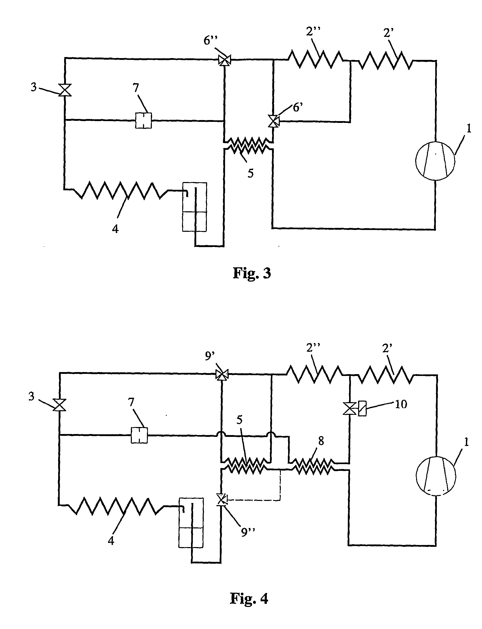
[0024] One possible arrangement for the invention is to lead the split stream through an already existing IHX 5. An arrangement for bypassing the main stream outside the IHX 5, and leading the split stream through the IHX 5, then has to be implemented. There are various solutions for this arrangement. One alternative is to use two three-way valves 6′ and 6″, as indicated in FIG. 3. One or both of three-way valves may for instance be replaced by two stop valves. The split stream is expanded directly to the low pressure side through an orifice 7 downstream of the IHX 5. The orifice 7 may be replaced by other expansion means, and valves may be installed upstream and / or downstream of the-expansion mean for closer flow control through the expansion mean 7.

example 2

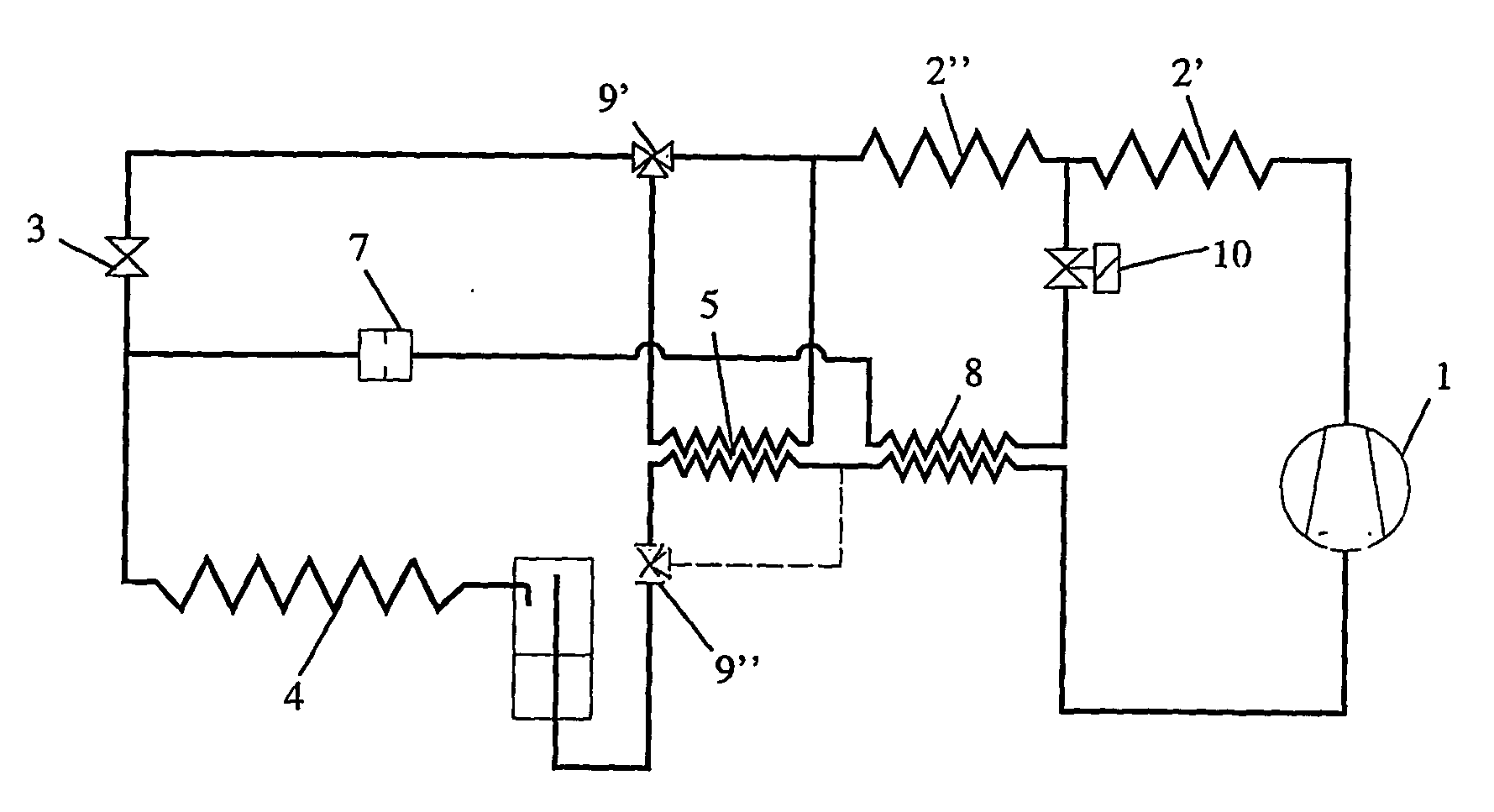
[0025] Another possibility is to install a separate heat exchanger 8, for instance a counterflow heat exchanger, for suction gas heating. This is illustrated in FIG. 4. When the evaporation temperature, or other usable temperatures, reaches a predetermined level, a split stream is carried through the suction gas heater 8 by opening the valve 10. This valve may be installed anywhere on the split stream line. The split stream is expanded directly to the low pressure side through an expansion mean, for instance an orifice 7 as indicated in FIG. 4. The IHX 5 can be avoided either by an arrangement on the high pressure side indicated be the three way valve 9′, or a equivalent arrangement on the low pressure side as indicated by dotted lines in figure X.

[0026] Suction gas superheat may be controlled by regulation of the spilt stream flow. This can for instance be performed by a metering valve in the split stream line. Another option is to apply a thermal expansion valve.

[0027] As explai...


PUM

PropertyMeasurementUnit
temperatureaaaaaaaaaa
exit temperatureaaaaaaaaaa
temperatureaaaaaaaaaa

Abstract

A compression refrigeration system includes a compressor (1), a heat rejector (2), expansion means (3) and a heat absorber (4) connected in a closed circulation circuit that may operate with supercritical high-side pressure.

Description

FIELD OF INVENTION [0001] The present invention relates to compression refrigeration system including a compressor, a heat rejector, an expansion means and a heat absorber connected in a closed circulation circuit that may operate with supercritical high-side pressure, using carbon dioxide or a mixture containing carbon dioxide as the refrigerant in the system. DESCRIPTION OF PRIOR ART AND BACKGROUND OF THE INVENTION [0002] Conventional vapour compression systems reject heat by condensation of the refrigerant at subcritical pressure given by the saturation pressure at the given temperature. When using a refrigerant with low critical temperature, for instance CO2, the pressure at heat rejection will be supercritical if the temperature of the heat sink is high, for instance higher than the critical temperature of the refrigerant, in order to obtain efficient operation of the system. The cycle of operation will then be transcritical, for instance as known from WO 90 / 07683. [0003] WO 94...

Claims


Application Information

Patent Timeline
Patent Type & Authority Applications(United States)
IPC IPC(8): F25B41/00C09K5/04F25B9/00F25B40/00F25B41/04
CPCF25B9/008F25B40/00F25B41/04F25B2309/061F25B2341/0661F25B2400/0403F25B2500/18F25B2600/2501F25B41/385F25B41/20
Inventor AFLEKT, KAREHAFNER, ARMINJAKOBSEN, ARNENEKSA, PETTERPETTERSEN, JOSTEINREKSTAD, HAVARDSKAUGEN, GEIRANDRESEN, TRONDTONDELL, ESPENELGSAETHER, MUNAN
Owner SINVENT AS
Learn More