Ophthalmic apparatus

a technology of ophthalmology and eyepieces, applied in the field of ophthalmology equipment, can solve the problems of inability to make the subject determine the location of the fixation mark, unstable vision fixation state of the eye, and measurement lasting forever, so as to improve the stability of the vision fixation state and stabilize the eye. fixation state. stable and smooth

Inactive Publication Date: 2006-06-22
CANON KK
View PDF6 Cites 36 Cited by
  • Summary
  • Abstract
  • Description
  • Claims
  • Application Information

AI Technical Summary

Benefits of technology

The present invention aims to improve the stability and smoothness of eye examination and observation by improving the stability of vision fixation state. This is achieved by providing an ophthalmic apparatus that includes a detection unit to detect the vision fixation state of the eye, a projection unit to project a fixation mark onto the fundus of the eye, and a fixation mark control unit to control the projection unit. The fixation mark control unit can change the presentation method of the fixation mark based on the detected vision fixation state, such as the brightness and size of the fixation mark and the operation of emphasizing its existence by applying stimulus to the subject. This makes it easier for the subject to stabilize their vision fixation and reduces the burden on them. The invention can be used in ophthalmic examinations to improve the accuracy and efficiency of the examination process.

Problems solved by technology

According to the ophthalmic apparatus in Japanese Patent Laid-Open No. 10-14878, if a subject to be examined is, for example, a person who has a visual disorder such as cataract or amblyopia or an infant, it is difficult to make the subject determine where the fixation mark is located.
As a result, the vision fixation state of the eye becomes more unstable, and the measurement lasts forever.
In this case, even if a large fixation mark is presented to the eye, the subject cannot recognize where the fixation mark is located, and it may be difficult to stabilize the line of sight.
If, therefore, a person who has poor eyesight, an infant, or the like is a subject to be examined, such a conventional ophthalmic apparatus cannot make the subject recognize where a fixation mark is located, and hence it is difficult to stabilize a vision fixation state.
As a consequence, the accuracy of automatic alignment deteriorates, and the reliability of examination deteriorates.
In some cases, alignment cannot be completed, and examination cannot be performed.

Method used


Image

  • Ophthalmic apparatus
  • Ophthalmic apparatus
  • Ophthalmic apparatus

Examples


first embodiment

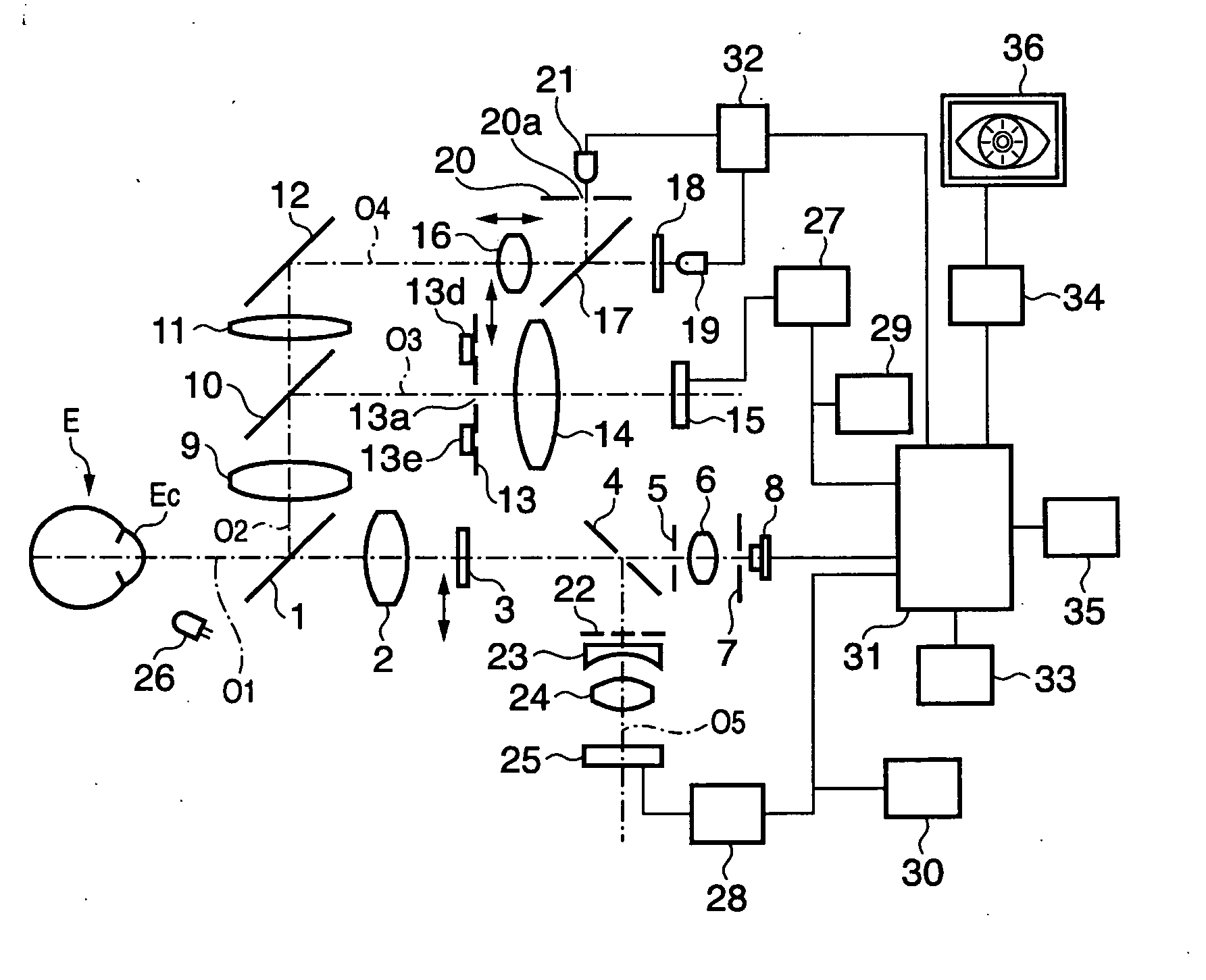
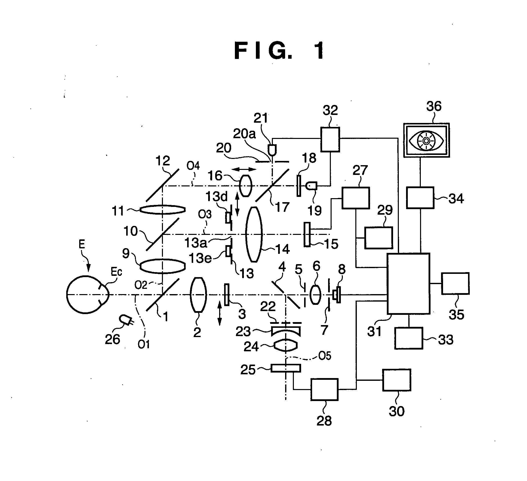
[0025]FIG. 1 is a view showing the arrangement of an ocular refractive power measuring apparatus (ophthalmic apparatus) according to the first embodiment of the present invention. On an optical axis O1 facing an eye E to be examined, there are sequentially arranged a dichroic mirror 1, an objective lens 2 for the measurement of an ocular refractive power, a diffuser 3 which is detachable with respect to the optical axis O1, a perforated mirror 4, a projection stop 5, a projection lens 6, an index plate 7 having a pinhole, and a light source 8 for the measurement of an ocular refractive power. These components constitute a measurement light projection system for the measurement of an ocular refractive power.

[0026] On an optical axis O2 in the reflecting direction of the dichroic mirror 1, there are arranged an objective lens 9 for the observation of the anterior ocular segment, a dichroic mirror 10 having the property of transmitting visible light and reflecting near-infrared light,...

second embodiment

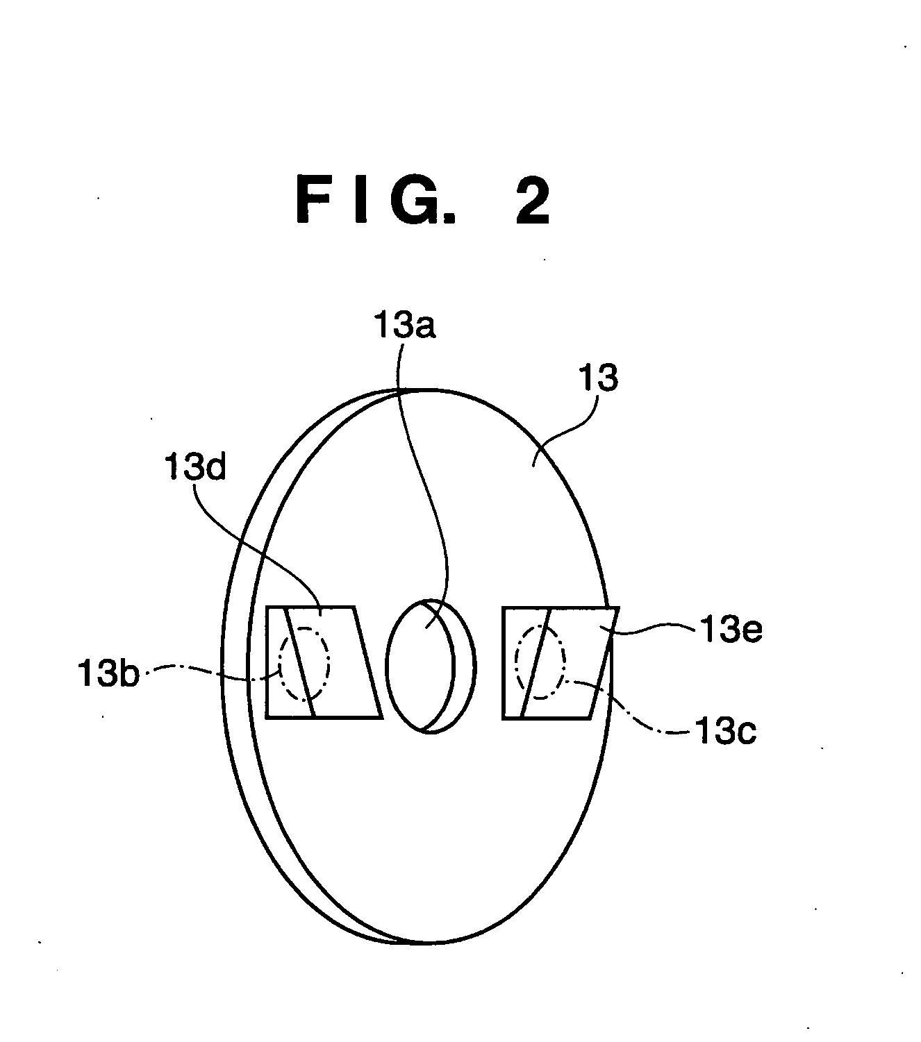
[0063]FIG. 6 is a view showing the arrangement of a fixation mark projection system according to the second embodiment of the present invention. The same reference numerals as in the first embodiment denote the same parts in the second embodiment. In addition, since an anterior ocular segment observation system, a projection system for ocular refractive power measurement light, an ocular refractive power measurement light-receiving system, an arithmetic processing unit 31, and the like, other than the fixation mark projection system, have the same arrangements as those in the first embodiment, an illustration thereof will be omitted.

[0064] In the fixation mark projection system of the second embodiment, a fixation mark 41 comprising, for example, liquid crystal panels shown in FIGS. 7A to 7C and a light source 42 for fixation mark illumination for a liquid crystal backlight for illuminating the fixation mark 41 are arranged on an optical axis O4. A fixation mark control unit 43 whi...


PUM


Abstract

There is disclosed an ophthalmic apparatus including a detection unit which detects a vision fixation state of an eye to be examined, a projection unit which projects a fixation mark onto a fundus of the eye, and a fixation mark control unit which controls the projection unit. The projection unit includes a changing unit which changes a fixation mark to be projected onto the fundus, and when a vision fixation state detected by the detection unit does not satisfy a predetermined criterion, the fixation mark control unit controls the changing unit to change a fixation mark to be projected onto the fundus.

Description

FIELD OF THE INVENTION [0001] The present invention relates to an ophthalmic apparatus which, for example, examines an eye to be examined or photographs the eye or observes it. BACKGROUND OF THE INVENTION [0002] In an ophthalmic apparatus designed to obtain information unique to an eye to be examined by projecting a light beam onto the eye and receiving the reflected light, a fixation mark for stabilizing a vision fixation state by fixing the eye is provided. [0003] There has recently been known an ophthalmic apparatus which includes a detection means for detecting a light beam projected onto the cornea or the like of an eye to be examined, and a driving means for moving an eye examination unit in the up and down direction, the left and right direction, and the back and forth direction, or any thereof, and aligns the eye with an apparatus optical system by controlling the driving means on the basis of the detected eye position. [0004] In such an ophthalmic apparatus, an examiner rou...

Claims


Application Information

Patent Timeline
Patent Type & Authority Applications(United States)
IPC IPC(8): A61B3/14
CPCA61B3/12A61B3/152A61F9/00781
Inventor IWANAGA, TOMOYUKI
Owner CANON KK
Why Eureka
Try Eureka