
Device capable of removing contaminants from a fluid

Inactive Publication Date: 2006-06-15
VALPEY RICHARD S III +4
View PDF22 Cites 42 Cited by
  • Summary
  • Abstract
  • Description
  • Claims
  • Application Information

AI Technical Summary

Benefits of technology

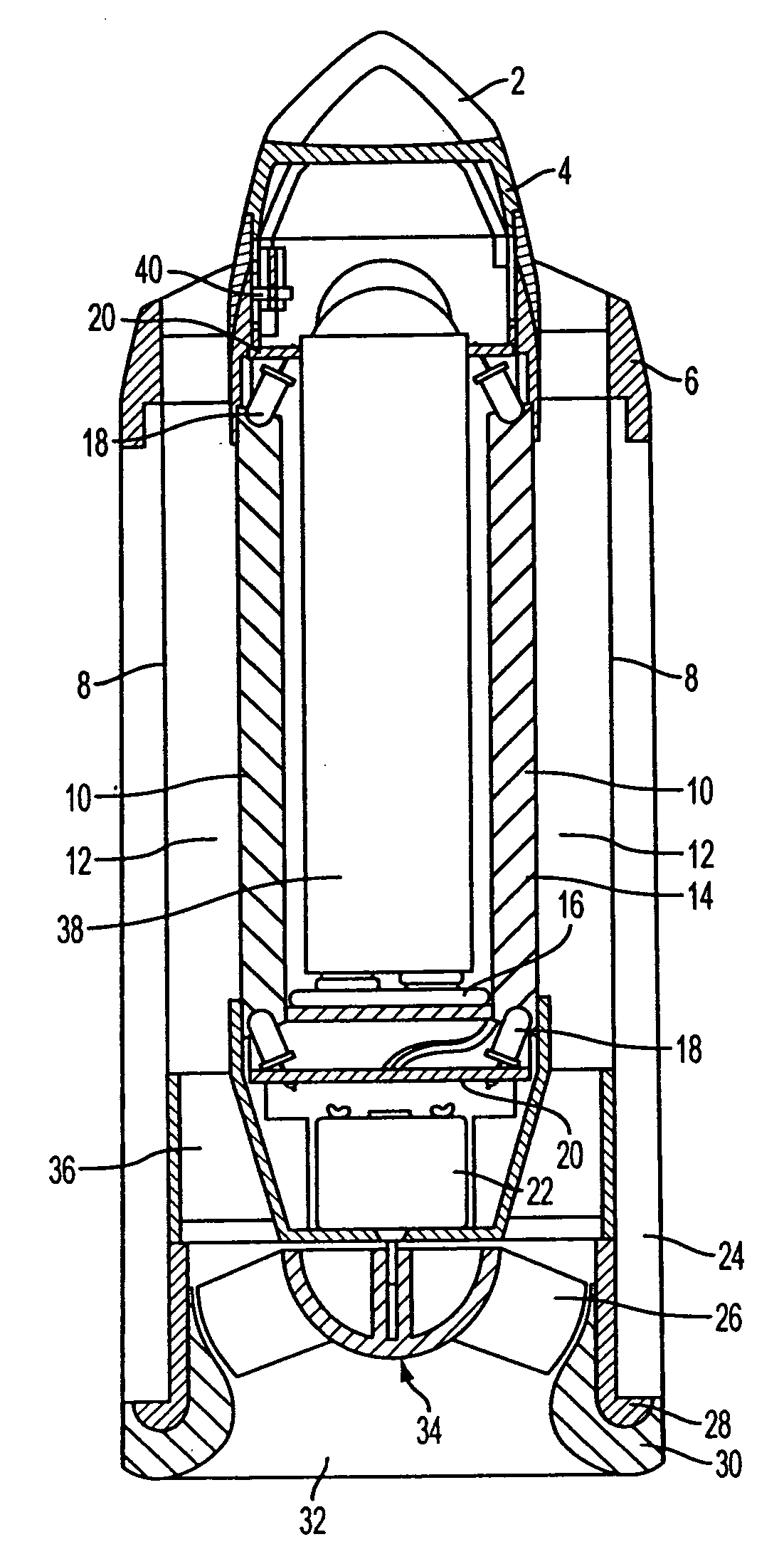
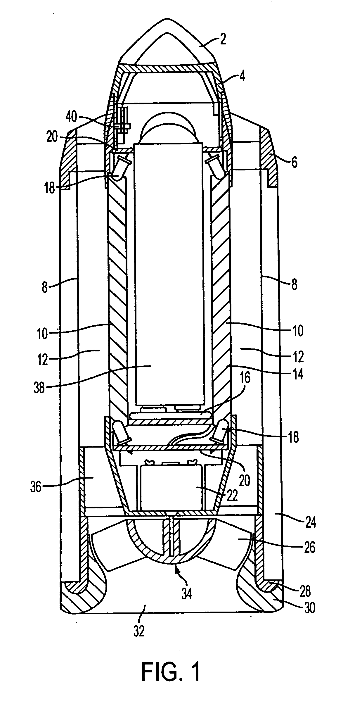
[0013] In one aspect, our invention provides a fluid purifying device comprising a chamber through which a fluid stream can flow, a photoreactive surface in the chamber, and a visible light source in the chamber. The photoreactive surface comprises a photocatalyst and a photosensitizer. The photosensitizer has a local maximum absorbance in the visible light range at a wavelength (λmax), such that the photoreactive surface is activatable by visible light having an intensity greater than about 10 mW / cm2 in the wavelength band of λmax±12 nm. The visible light source is positioned in the chamber and delivers visible light to the photoreactive surface at an intensity greater than about 10 mW / cm2 in the wavelength band of λmax±12 nm. The activated photoreactive surface reduces or eliminates contaminants in the fluid stream.
[0030] In another aspect, our invention provides a fluid purifying device comprising a chamber through which a fluid stream can flow, a photoreactive surface in the chamber, and a visible light source in the chamber. The photoreactive surface is activated by visible light having an intensity of at least about 90 mW / cm2. The visible light source is positioned in the chamber and delivers a light intensity to the photoreactive surface of at least about 90 mW / cm2. The activated photoreactive surface reduces or eliminates contaminants in the fluid stream. The device can preferably be operated to purify the air in a room.
[0040] In another aspect, our invention provides a fluid purifying device comprising: a chamber through which a fluid stream can flow; a photoreactive surface in the chamber that is activated by visible light and that comprises a Ti—O—N constitution in which nitrogen (N) is incorporated in titanium oxide crystal; and a visible light source in the chamber, wherein the activated photoreactive surface reduces or eliminates contaminants in the fluid stream. Our invention also provides a method of purifying the air in a room using such a device.

Problems solved by technology

However, conventional fluid purifying devices are deficient in various respects.
For example, they often contain absorbents, such as activated carbon, which impose back pressure limitations on the devices, causing relatively slow migration of air through the devices for purification.
These limitations, in turn, prevent such devices from being able to rapidly remove airborne contaminants from the air.
To overcome the back pressure limitations and to allow for more rapid removal of contaminants, relatively large amounts of energy are required to move air through the devices, making them inefficient.
Another problem with conventional fluid purifying devices is that they are expensive and somewhat dangerous to operate since they utilize ultraviolet light.
High ozone levels damage lung tissue.
However, we do not believe that these patents actually teach a person of ordinary skill in the fluid purifying device art how, without undue experimentation, to practice a method or to make and / or use a device which is capable of removing contaminants from a fluid, particularly air, using visible light (i.e., between about 400 nm and about 700 nm).
Consequently, the Watanabe, et al. patent does not describe an air purifying system that operates using a photocatalyst that is, in fact, photoexcited by visible light wavelengths.
However, for reasons that will be discussed below, we have found that, while the reactor described in the Say, et al. patent might operate successfully to remove contaminants in a fluid stream when exposed to ultraviolet light at the disclosed average activating light intensities, that reactor is not operable in the visible light range at such light intensities.
However, the Carmignani, et al. patent provides no details as to how to render such a visible light system operable.
This increases the frequency of contact between harmful substances and the photdcatalyst, such that the harmful substances are decomposed at a high decomposition rate.
However, like the Carmignani, et al. patent, the Aoyagi patent publication provides no details as to how to render the visible light system operable.

Method used


Image

  • Device capable of removing contaminants from a fluid
  • Device capable of removing contaminants from a fluid
  • Device capable of removing contaminants from a fluid

Examples


example 1

Preparation of Photosensitized Titanium Dioxide

[0110] This example describes the preparation of photosensitized titanium dioxide using various ruthenium-based photosensitizers. The procedure utilized here generally follows the procedure set forth in U.S. Pat. No. 6,245,988 B1 to Grätzel, et al., referred to previously and incorporated herein by reference in its entirety (see, for e.g., column 13, line 40 to column 14, line 47), with a few variations as described below.

A. Photosensitizer is cis-bis(isocyanato) (2,2′bipyridyl-4,4′dicarboxylato)ruthenium (II)

[0111] Aggregated particles of titanium dioxide available commercially (e.g., Nanotek TL-1501-000-025, supplied by Nanophase, Burr Ridge, Ill.) were broken down into separate particles, as described in the Grätzel, et al., patent. Thereafter, surface moisture on titanium dioxide was removed. One gram of titanium dioxide was heated to 500 degrees Centigrade for 30 minutes. The resulting dry powder was allowed to cool under argon....

example 2

Odor Removal Experiment

[0115] A. Control (Ultraviolet Light Plus Titanium Dioxide)

[0116] Gas mixtures of a tracer molecule (i.e., isopropyl alcohol) in purified air were generated using a Kin-Tek 485 precision gas standards generator. The generator was set to deliver 8 parts per million of the molecule in purified air. The gaseous mixture was passed into a chamber (R J Harvey, Hillsdale, N.J.) and through a 9 cm number 42 Whatman filter paper containing titanium dioxide (1 gram, Nanotek TL-1501-000-025, supplied by Nanophase, Burr Ridge, Ill.). The chamber was cylindrical, with a 3.5 inch diameter and 2 inch length (i.e., a volume of about 19 sq. inches) and a flow rate through the chamber of 32,000 nL, min. The gas stream exiting the chamber was analyzed by gas chromatography.

[0117] The photocatalytic reaction was driven by a 500 W Xenon arc lamp. The infrared component (heat) was removed from the light beam using a water filter (ThermoOriel, part# 61945) and the wavelength rang...

example 3

Light Intensity Requirements for our Fluid Purifying Device

[0126] This example provides experimental results showing that a fluid purifying device using visible light to excite photosensitized titanium dioxide requires approximately two orders of magnitude greater light intensity compared to that required by one using ultraviolet light and titanium dioxide.

[0127] In this example, three experiments were performed. The three experiments used materials described previously in Examples 1 and 2. The model contaminant molecule sought to be removed in this experiment was isopropyl alcohol. Two of the experiments utilized visible light and titanium dioxide coated with photosensitizer (Ru-535; see experimental procedure for preparation of this photoreactive surface in Example 1). The other experiment utilized ultraviolet light and bare titanium dioxide. The two visible light experiments were conducted at two total light intensities, namely between about 1-2 mW / cm2 and at about 94 mW / cm2. T...


PUM

PropertyMeasurementUnit
Poweraaaaaaaaaa
Flow rateaaaaaaaaaa
Light intensityaaaaaaaaaa

Abstract

A fluid purifying device having various embodiments, each of which is capable of removing airborne molecules, such as contaminants, malodors, volatile organic compounds (VOCs), pathogens, mold and bacteria, using the combination of visible light and a photocatalyst that has been either treated with a photosensitizer or has been treated in some other manner to lower the energy required to activate the photocatalyst (i.e., by having it generate free radicals) to that emitted by visible light bulbs. Preferably, the device is an air purifying device; however, the device could also be used as a liquid (e.g., water) purifying device.

Description

FIELD OF THE INVENTION [0001] This invention relates to methods of removing contaminants, such as malodors, volatile organic compounds (VOCs), pathogens, mold and bacteria from a fluid, such as air or water, using a combination of light and a photocatalyst. In particular, this invention relates to fluid purifying devices that incorporate this kind of technology. BACKGROUND OF THE INVENTION [0002] In the presence of moisture or oxygen, the combination of ultraviolet light and titanium dioxide yields free radicals. These free radicals remove contaminants from fluids, such as air or water. This technology, which is well known, has been applied to air and water purifying devices. [0003] For example, U.S. Pat. No. 4,892,712 to Robertson, et al. relates to a device that removes, reduces or detoxifies organic pollutants from a fluid, such as air or water, by causing the fluid to contact a matrix made of a substrate onto which a fixed anatase TiO2 or other photoreactive metal semiconductor ...

Claims


Application Information

Patent Timeline
IPC IPC(8): C07C1/00B01D47/00B01D53/00C02F1/78B01J19/12B01D46/00
CPCA61L9/205B01D53/007B01D53/885B01D2255/802B01D2259/802C02F1/30C02F1/725C02F2101/322C02F2303/04C02F2305/10
Inventor VALPEY, RICHARD S. IIIADAIR, JOEL E.VARANASI, PADMA PRABODHJONES, MATTHEW A.PLANKENBORN, DANIEL J.
Owner VALPEY RICHARD S III
Learn More