Mask blanks production method and mask production method

a mask and production method technology, applied in the field of mask blank production methods and mask production methods, can solve the problems of difficult to effectively prevent foreign matters, difficult to suppress the dust caused, and extremely difficult to suppress the dust itself, so as to prevent the pollution caused by the dust, the effect of suppressing the dust itsel

Active Publication Date: 2006-06-08
HOYA CORP
View PDF6 Cites 3 Cited by
  • Summary
  • Abstract
  • Description
  • Claims
  • Application Information

AI Technical Summary

Benefits of technology

[0042] In addition, in the mask blank having resist, it is preferable to remove an unnecessary resist film on the peripheral edge of the substrate before forming the dust-free protective film, to remove the dust-free protective film of the contact part on the peripheral edge of the substrate after forming the dust-free protective film, or to remove the unnecessary parts of both the resist film and the dust-free protective film. By the dust-free protective film, the surface of the blank is protected from direct adhesion of dust. However, the generation of the dust itself can be suppressed by previously removing the unnecessary film from the peripheral edge of the substrate or the contact part, thereby preventing pollution caused by the dust, for example, in the forming step or the removing step of the dust-free protective film.

Problems solved by technology

However, it has been found that even in the case of the mask blank which selectively removes the unnecessary resist film on the peripheral edge of the substrate by the above-described method, etc., the trouble as will be explained below is involved.
For this reason, it is extremely difficult to suppress dusting caused by the frictions of all the above-described contact parts.
As a result, it has been found that it is extremely difficult to effectively prevent foreign matters from adhering to the surface (that is a resist film (uppermost layer)) of the mask blank or building-up thereon, during moving, transporting, and storing the mask blank with the mask blank contained in a storage container.

Method used


Image

  • Mask blanks production method and mask production method
  • Mask blanks production method and mask production method
  • Mask blanks production method and mask production method

Examples


example 1

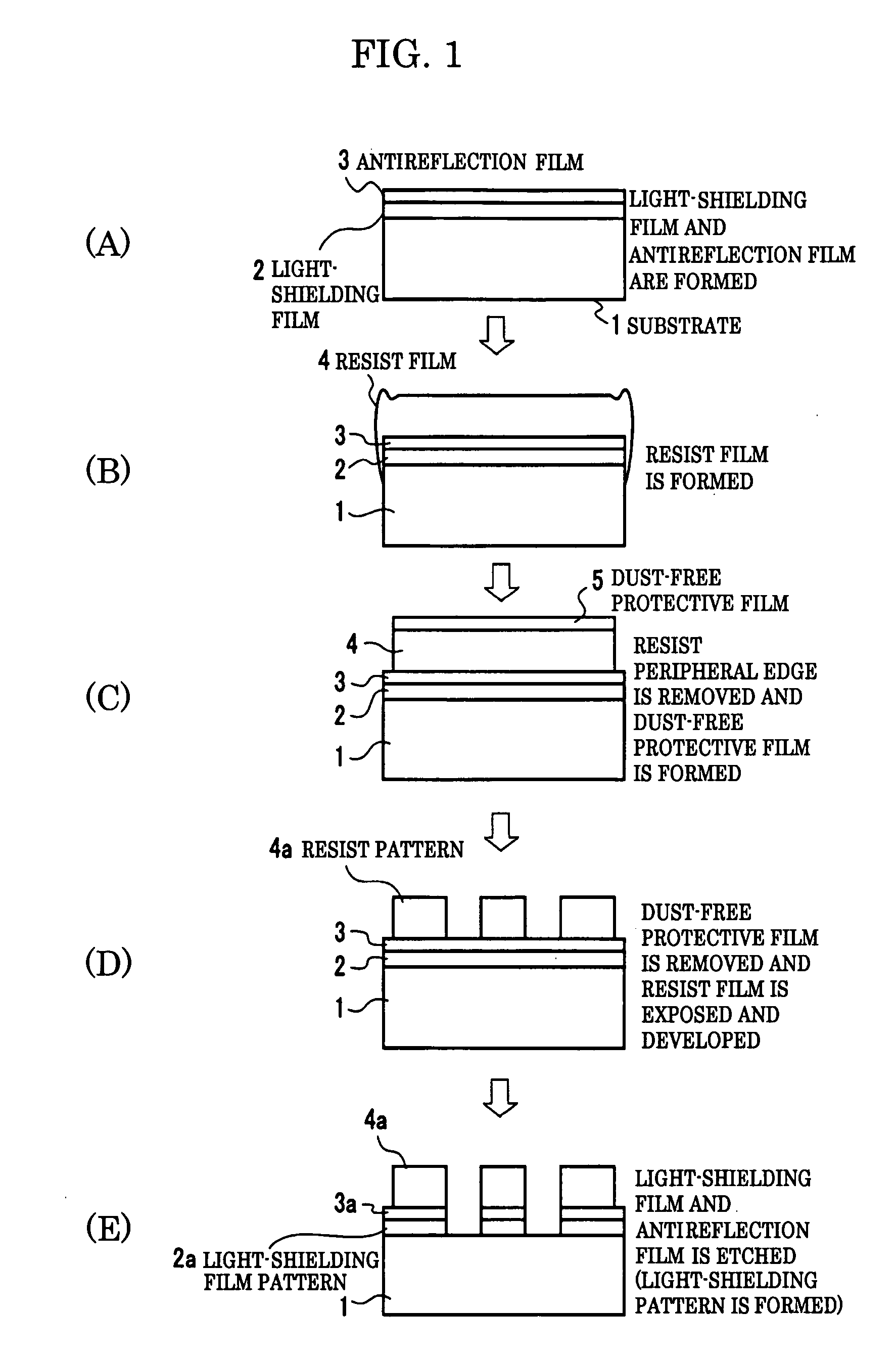
[0053] First, a mask blank is manufactured. As shown in FIG. 1(A), a light-shielding film 2 of 45 nm thickness containing chrome as a main composition was formed by sputtering on a suitably polished synthetic quartz substrate 1 of 6 inch×6 inch length and 0.25 inch thickness. Subsequently, an antireflection film 3 of 25 nm thickness containing chrome oxide as a main composition was formed on the light-shielding film 2 by sputtering.

[0054] Next, as shown in FIG. 1(B), a resist 4 (Chemically amplified positive resist for electron beam light exposure FEP171: developed by FUJIFILM Arch Co, Ltd.) was spin-coated on an antireflection film 3 so that the film thickness after heating and drying treatment becomes 300 nm.

[0055] Next, as shown in FIG. 1(C), an unnecessary resist formed on the peripheral edge of the substrate 1 was removed and a dust-free protective film 5 was formed on the resist film 4. In this case, in removing the unnecessary resist, the known apparatus for removing unnece...


PUM

PropertyMeasurementUnit
lengthaaaaaaaaaa
lengthaaaaaaaaaa
lengthaaaaaaaaaa

Abstract

To prevent foreign matters from adhering to a substrate, etc., thereby causing inconveniences during storing and transporting a mask blank, or during manufacturing the mask blank and a mask. Thin films 2 and 3 formed in a mask thin film forming step of a mask blank manufacturing steps are covered by a dust-free protective film 5 formed of water-soluble material, thereby preventing foreign matters from adhering to the surface of the mask blank itself and preventing the surface of the mask blank from being damaged in the subsequent step, and when the mask blank is used, the dust-free protective film is removed.

Description

TECHNICAL FIELD [0001] The present invention relates to a method of manufacturing a mask blank, which is a mask material of a mask for pattern transfer, and a manufacturing method for a mask. BACKGROUND ART [0002] For example, a mask blank, which is a raw material of a mask (reticule) used for a photolithography method, has a structure in which various kinds of thin films such as a light-shielding film, which is also referred to as an opaque film, and a phase shift film optically relating to a transfer exposure light are formed on a substrate surface, and further, a resist film is formed on an uppermost layer of each kind of the thin film, or an antireflection film and a conductive film are formed on or under the resist film, and further a protective film, etc., for protecting the thin films is formed. [0003] A specific example of this mask blank includes a mask blank having resist, whose uppermost layer is a resist film. The mask blank having resist is formed in such a manner that ...

Claims


Application Information

Patent Timeline
Patent Type & Authority Applications(United States)
IPC IPC(8): G03F1/00G03F1/50G03F1/68G03F1/80H01L21/027
CPCG03F1/48H01L21/0271G03F1/50
Inventor KOBAYASHI, HIDEO
Owner HOYA CORP
Why Eureka
Try Eureka