Light source unit and image display unit
a technology of light source and image display unit, which is applied in the direction of instruments, lighting and heating equipment, transportation and packaging, etc., can solve the problems of difficult to provide laser lights at substantially the same spaces and difficult to apply laser lights to exact positions
- Summary
- Abstract
- Description
- Claims
- Application Information
AI Technical Summary
Benefits of technology
Problems solved by technology
Method used
Image
Examples
first embodiment
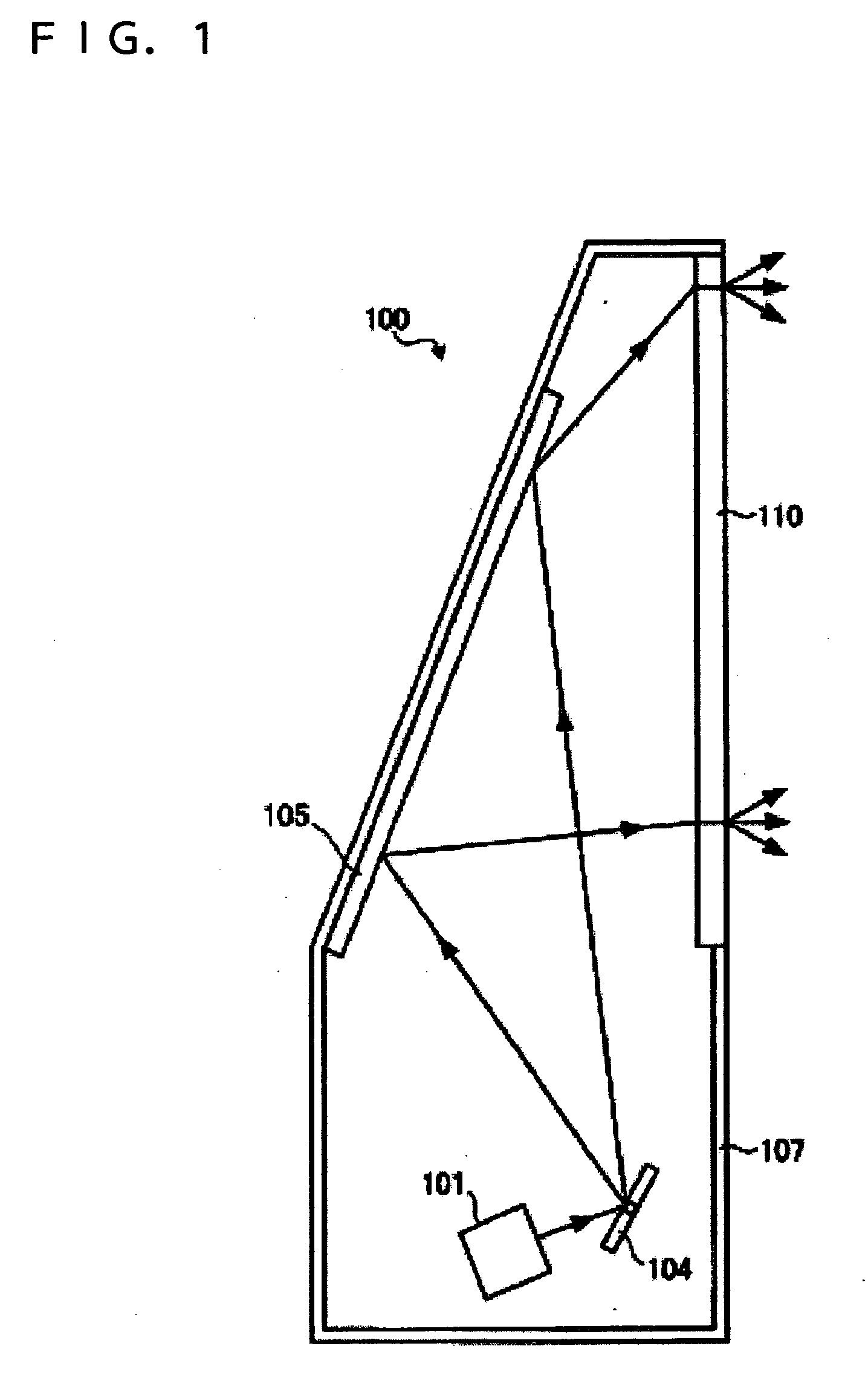
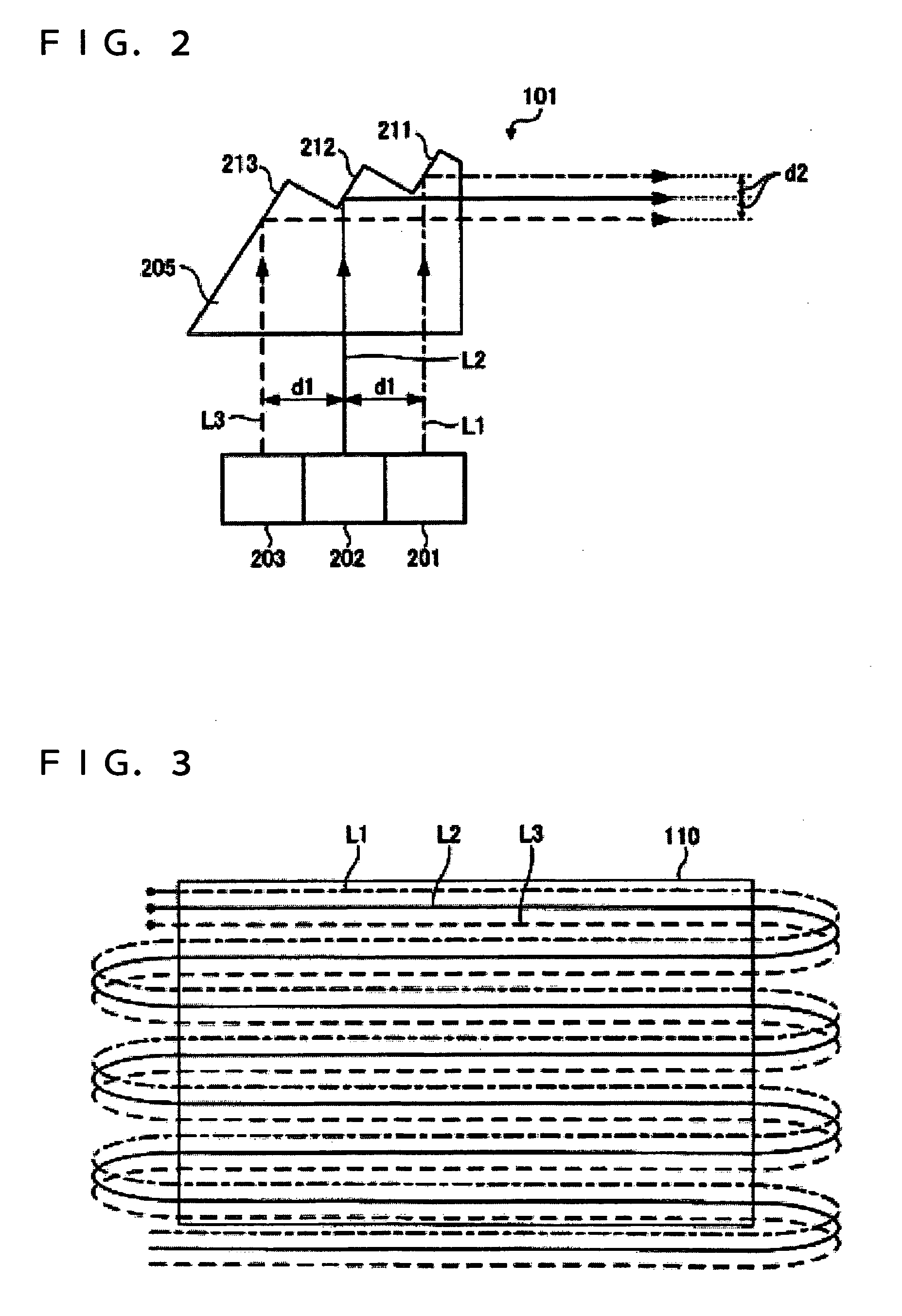
[0026]FIG. 1 is a schematic diagram of an image display unit 100 according to a first embodiment of the invention. The image display unit 100 is a so-called rear projector for displaying images in such a way that laser beam light that is applied onto one surface of a screen 110 and is output from the other surface of the screen 110 is displayed. A light source unit 101 applies laser light responsive to an image signal toward a galvano mirror 104. The galvano mirror 104 reflects the laser light from the light source unit 101 toward a reflecting mirror 105.
[0027] The galvano mirror 104 is a scanning section for applying the light from the light source unit 101. The galvano mirror 104 applies laser light in a two-dimensional direction by rotating around specified two shafts interesting at right angles. The galvano mirror 104 can be manufactured by, for example, micro electro mechanical system (MEMS) technology. The reflecting mirror 105 is provided on the inner surface of a casing 107...
second embodiment
[0043]FIG. 5 is a schematic diagram of a light source unit 501 according to a second embodiment of the invention. The same components as those of the light source unit 101 according to the first embodiment are given the same reference numerals and their duplicate description will be omitted. The light source unit 501 includes a convergent lens 511 and a divergent lens 512. The convergent lens 511 and the divergent lens 512 serve as optical-path changing sections for changing the optical paths of the color lights. Substantially parallel color lights are incident on the convergent lens 511. The convergent lens 511 is a convex lens that converges the color lights from the light sources 201, 202, and 203.
[0044] The lights from the convergent lens 511 are incident on the divergent lens 512. The divergent lens 512 is a concave lens that diverges the lights from the convergent lens 511 into substantially parallel lights. Thus the color lights from the light sources 201, 202, and 203 are o...
third embodiment
[0046]FIG. 6 is a schematic diagram of a light source unit 601 according to a third embodiment of the invention. The same components as those of the light source unit 101 according to the first embodiment are given the same reference numerals and their duplicate description will be omitted. The light source unit 601 includes a prism element 605 that transmits color lights. The prism element 605 serves as an optical-path changing section for changing the optical paths of the color lights. The prism element 605 can be made of a glass material or a transparent resin material, as is the prism element 205 according to the first embodiment. The prism element 605 can be formed by cutting or injection molding.
[0047] The prism element 605 has a triangular shape. Substantially parallel color lights are incident on the prism element 605. The color lights incident on the prism element 605 are refracted by a light-exiting plane 611. The light-exiting plane 611 serves as a refracting interface t...
PUM
 Abstract
Description
Claims
Application Information
 - R&D
- Intellectual Property
- Life Sciences
- Materials
- Tech Scout
- Unparalleled Data Quality
- Higher Quality Content
- 60% Fewer Hallucinations
Browse by: Latest US Patents, China's latest patents, Technical Efficacy Thesaurus, Application Domain, Technology Topic, Popular Technical Reports.
© 2025 PatSnap. All rights reserved.Legal|Privacy policy|Modern Slavery Act Transparency Statement|Sitemap|About US| Contact US: help@patsnap.com


