
Arc tube of discharge lamp and method of manufacturing of arc tube

Inactive Publication Date: 2006-06-08
KOITO MFG CO LTD
View PDF2 Cites 11 Cited by
  • Summary
  • Abstract
  • Description
  • Claims
  • Application Information

AI Technical Summary

Benefits of technology

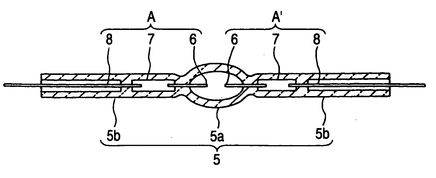
[0016] The total weight of the substance (metal halide) enclosed as the pellet P in the closed glass bulb 5a is 0.3-0.4 mg at the most, while the weight of each electrode assembly A, A′ is about 75 mg (the total weight of the two assemblies is about 150 mg). Therefore, even if the pellet P and the electrode assembly A, A′ have the same water content, the electrode assembly A, A′ is much larger in total quantity of water. Therefore, the inventors have thought that it is effective for prevention of the occurrence of flicker to lessen the water content of the electrode assembly A, A′.
[0018] The inventors have thought this reason as follows: though the impurity (water and oxide film) is removed from the electrode rod 6, the molybdenum foil 7, and the lead wire 8 once by the impurity (water and oxide film) removing treatment performed on the parts level, when the electrode rod 6, the molybdenum foil 7, and the lead wire 8 are thereafter welded (joined) in the air to be integrally formed as the electrode assembly A, A′, the impurity (water and oxide film) is attached again to the electrode assembly A, A′, so that the occurrence of flicker is promoted, or energy is used in excitation of the impurity, so that the luminous flux lowers or the starting voltage of the arc tube becomes high.
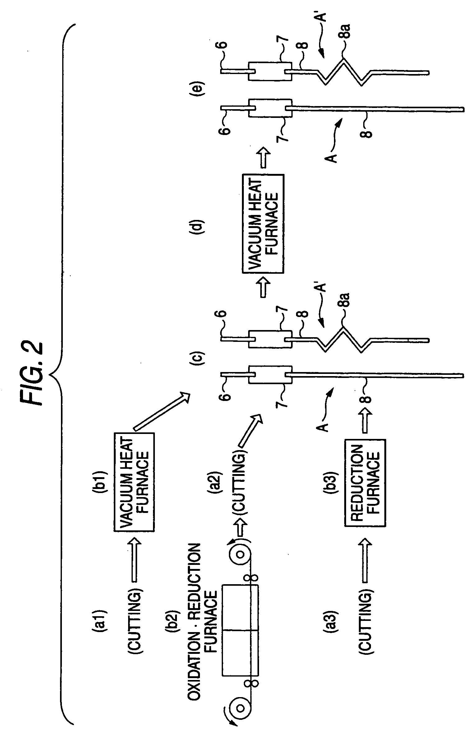
[0027] Since the electrode rod in the electrode assembly receives the impurity removing treatment twice, the quantity of the impurity (water and oxide film) attached to the electrode assembly is correspondingly small, and the quantity of water and gas as the impurity enclosed in the closed glass bulb is correspondingly small. Therefore, this treatment is effective for prevention of the occurrence of flicker.
[0028] Particularly, in the electrode rod that has received the vacuum heat treatment at the high temperature of 1600-2200° C., not only the water and the oxide film that are attached on the surface of the electrode rod but also impurity (water and foreign substance) inside the electrode rod can be removed. The higher this vacuum heat treatment temperature is, the higher the impurity (water and foreign substance) removal effect is. However, simultaneously, coarsening of the crystal progresses and the electrode rod becomes easy to bend. Therefore, it is desirable that the treatment temperature suited to the diameter of the electrode rod is selected (for example, in the electrode rod having the diameter of 0.25 mm, the treatment temperature is set to about 1600° C.).
[0030] Since the molybdenum foil in the electrode assembly receives the impurity removing treatment twice, the quantity of the impurity (water and oxide film) attached to the electrode assembly is correspondingly small, and the quantity of water and gas as the impurity enclosed in the closed glass bulb is correspondingly small. Therefore, this treatment is effective for prevention of the occurrence of flicker. Further, the oxidation / reduction treatment applied to the molybdenum foil before being integrally formed as the electrode assembly works so as to increase surface roughness of the molybdenum foil and increase air tightness with the glass layer.
[0032] Since the molybdenum lead wire in the electrode assembly receives the impurity removing treatment twice, the quantity of the impurity (water and oxide film) attached to the electrode assembly is correspondingly small, and the quantity of water and gas as the impurity enclosed in the closed glass bulb is correspondingly small. Therefore, this treatment is effective for prevention of the occurrence of flicker.

Problems solved by technology

Any tests have undesirable results.

Method used


Image

  • Arc tube of discharge lamp and method of manufacturing of arc tube
  • Arc tube of discharge lamp and method of manufacturing of arc tube
  • Arc tube of discharge lamp and method of manufacturing of arc tube

Examples


Embodiment Construction

[0056] Embodiments of the invention will be described with reference to the accompanying drawings.

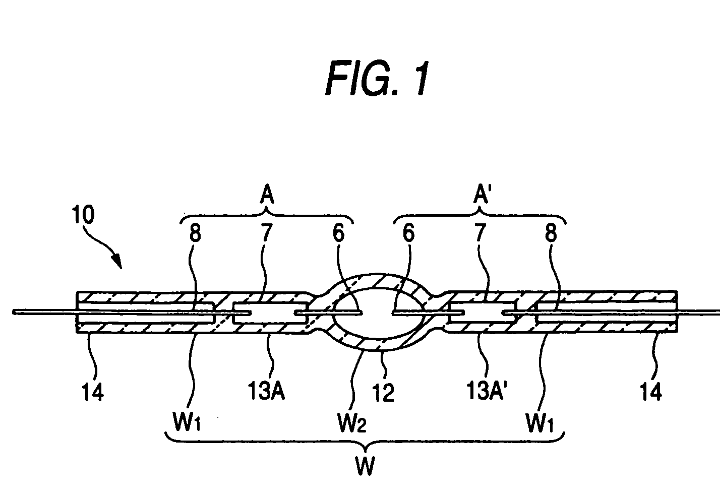
[0057] FIGS. 1 to 6 show one embodiment of the invention. FIG. 1 is a longitudinal section of a mercury-free arc tube for discharge lamp in one embodiment of the invention; FIG. 2 is a process drawing that shows a pretreatment step in a manufacturing process of the arc tube; FIGS. 3(a) to 3(f) are process drawings that show the manufacturing process of the arc tube, in which FIG. 3(a) is an explanatory view of a provisional pinch seal step in a primary pinch seal step, FIG. 3(b) is an explanatory view of a normal pinch seal step in the primary pinch seal step, FIG. 3(c) is an explanatory view of putting-in of a pellet of a light emitting substance, FIG. 3(d) is an explanatory view of an insertion step of a second electrode assembly, FIG. 3(e) is an explanatory view of a tip-off step (temporarily electrode assembly fixing-step), and FIG. 3(f) is an explanatory view of a secondary pinch ...


PUM


Abstract

In an arc tube for discharge lamp, an electrode assembly is formed by integrally joining an electrode rod, a molybdenum foil, and a molybdenum lead wire. The electrode assembly is sealed into pinch seal portions located at both ends of a glass tube. The electrode assembly, before being pinch-sealed into the pinch seal portions, receives vacuum heat treatment at 200 to 800° C. Hereby, the water content of the assembly is adjusted to 10 ppm or less, and desirably to 3 ppm less and an oxide film attached to the surface of the electrode assembly is removed. Therefore, the quantity of impurity (water or gas) enclosed in the closed glass bulb is very small, so that it is possible to provide an arc tube in which the flicker is not produced, luminous flux of 3000 lm or more is obtained, and starting voltage can be lowered to about 15 kV.

Description

[0001] The present application claims foreign priority based on Japanese Patent Application No. P.2004-349481, filed on Dec. 2, 2004, the contents of which are incorporated herein by reference. BACKGROUND OF THE INVENTION [0002] 1. Field of the Invention [0003] The present invention relates to an arc tube of discharge lamp and a method of manufacturing an arc tube. [0004] 2. Related Art [0005]FIG. 7 shows a discharge lamp of related art. A front end portion of an arc tube 5 is supported by a single lead support 2 that protrudes forward of an insulating base 1, and a rear end portion of the arc tube 5 is supported by a recess part 1a of a base 1, and further a rear-end-side portion of the arc tube 5 is gripped by a metallic support member S fixed to a front surface of the insulating base 1. [0006] A front-end-side lead wire 8 that is led out from the arc tube 5 is fixed to the lead support 2 by welding, while a rear-end-side lead wire 8 is fixed, through a bottom wall 1b that forms t...

Claims


Application Information

Patent Timeline
IPC IPC(8): H01J17/20H01J61/12H01J9/04H01J9/18H01J9/02H01J9/32H01J61/073H01J61/36
CPCH01J9/247H01J9/28H01J9/326
Inventor HOMMA, AKIRAFUKUYO, TAKESHITAKAGAKI, MICHIOMISONOU, SHINYA
Owner KOITO MFG CO LTD
Learn More