
Method and apparatus for security over multiple interfaces

a technology of multiple interfaces and methods, applied in the field of integrated circuit chips, can solve the problems of all subsequent (e.g., lower) levels being compromised, and affecting the security of multiple interfaces

Active Publication Date: 2006-06-01
AVAGO TECH INT SALES PTE LTD
View PDF20 Cites 15 Cited by
  • Summary
  • Abstract
  • Description
  • Claims
  • Application Information

AI Technical Summary

Benefits of technology

The invention is a method and system for securely authenticating and exchanging data among multiple integrated circuits (ICs). The system includes multiple ICs that communicate with each other using a secure digital system. Each IC has a unique key generator for generating a cipher key, a memory for securely storing the key, an authenticating module for verifying the identity of neighboring ICs, an encryption module for encrypting data communicated from one IC to another, and a decryption module for decrypting data received from another. The method involves generating a unique cipher key for each IC, securely storing the key in each IC, authenticating neighboring ICs, and encrypting data communicated between ICs. This ensures that data is exchanged securely and prevents unauthorized access. The invention can be used in various digital systems such as computer networks or embedded systems.

Problems solved by technology

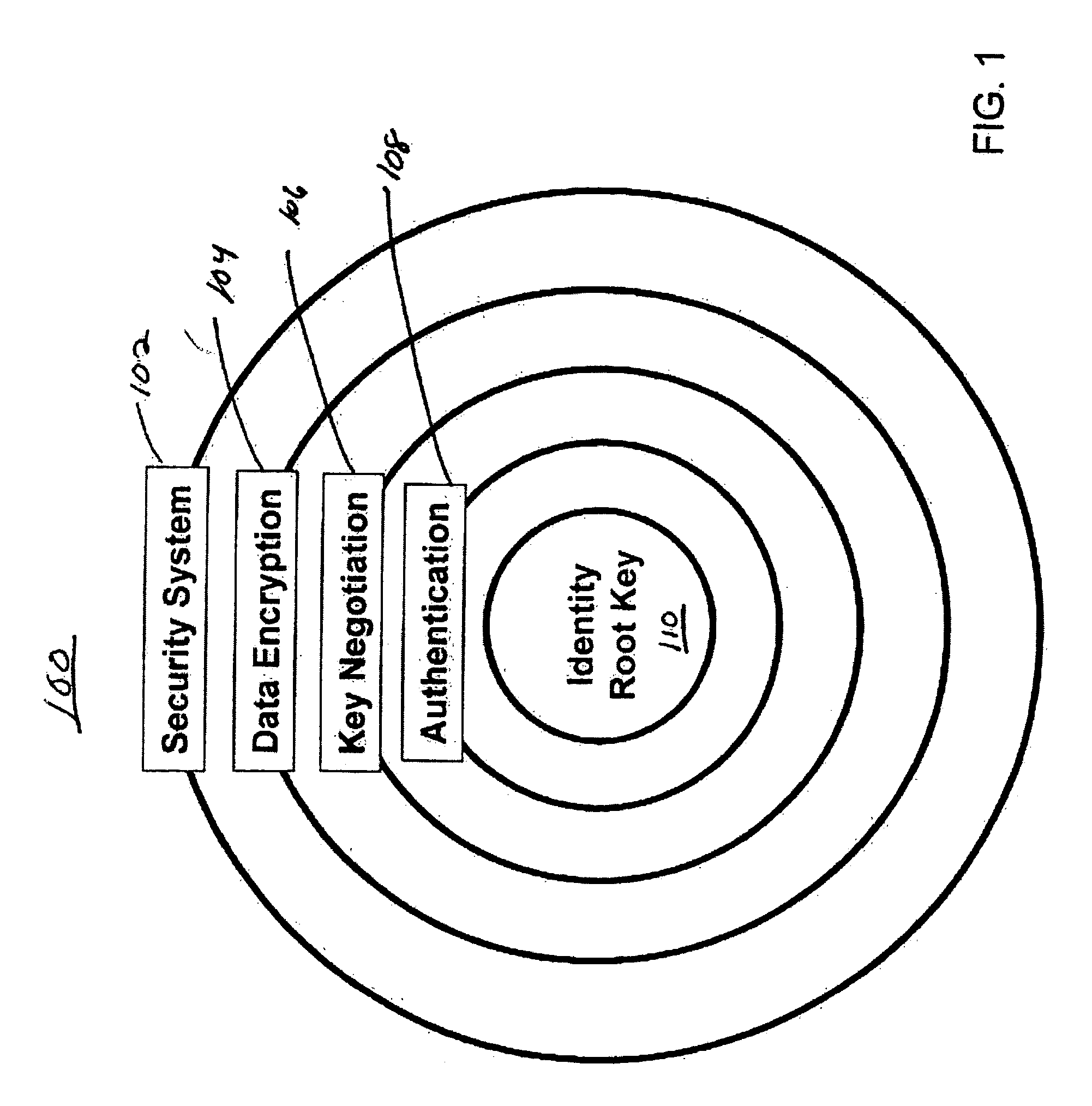
If the key negotiation is not secure (e.g., the keys are subject to interception by unauthorized persons), the encrypted data may be compromised.
In contrast, once a higher level key is compromised, all subsequent (e.g., lower) levels may be compromised.
Moreover, higher level keys tend to be used for relatively long periods of time.
Thus, the potential for harm is much greater.
All of these aspects of the system are susceptible to attacks by hackers, viruses or other means.
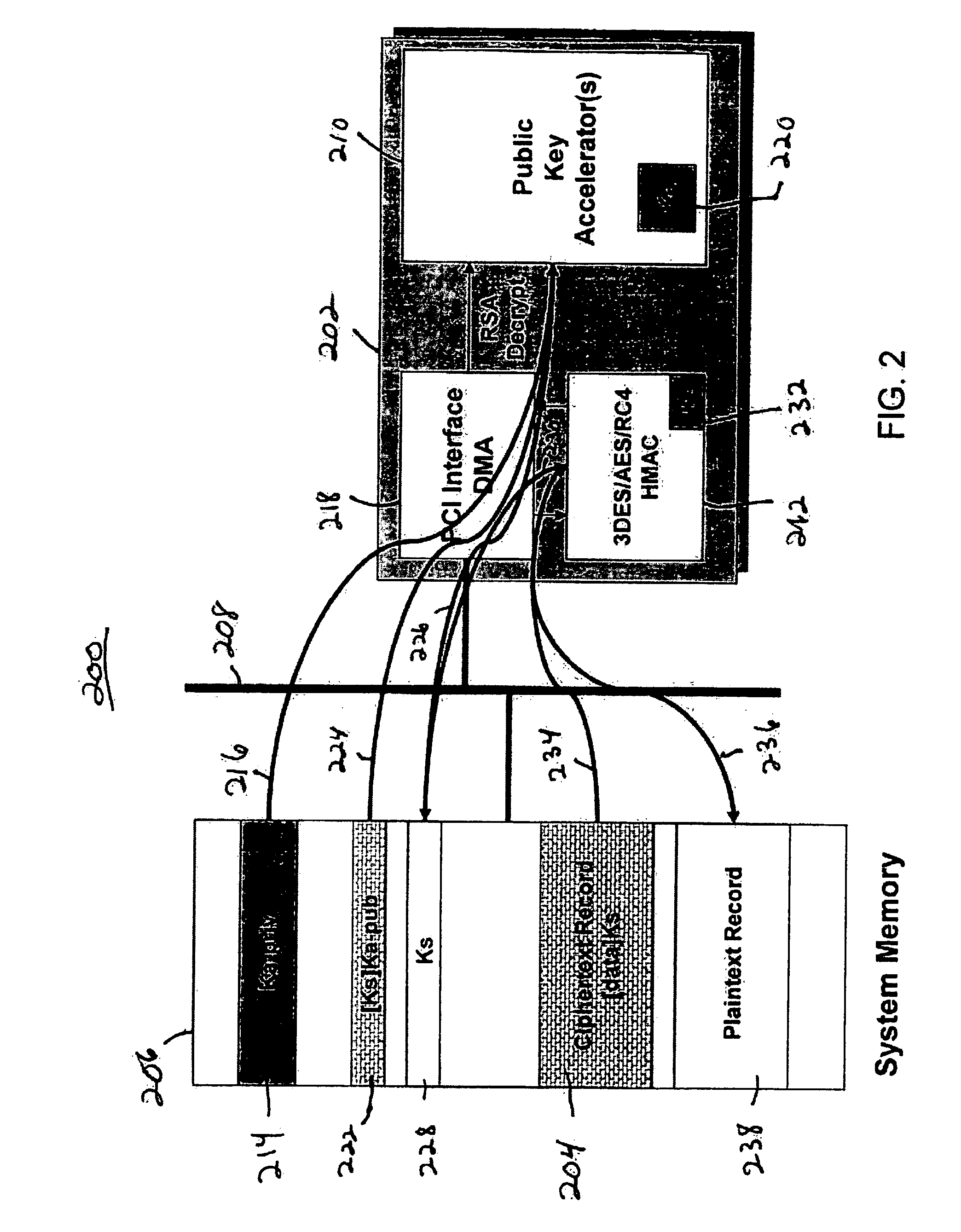
Given that in an SSL transaction the client's private key is essentially a certificate that identifies the server (hence it may essentially comprise the server's private key), conventional architectures such as this may not provide sufficient security for many applications.
However, these hardware modules or devices are not per se authenticated.
Moreover, even the most sophisticated data security schemes are prone to security breaches at the component level.
However, this approach makes testing, debugging and repairing of the PCBs unreasonably difficult.

Method used


Image

  • Method and apparatus for security over multiple interfaces
  • Method and apparatus for security over multiple interfaces
  • Method and apparatus for security over multiple interfaces

Examples


Embodiment Construction

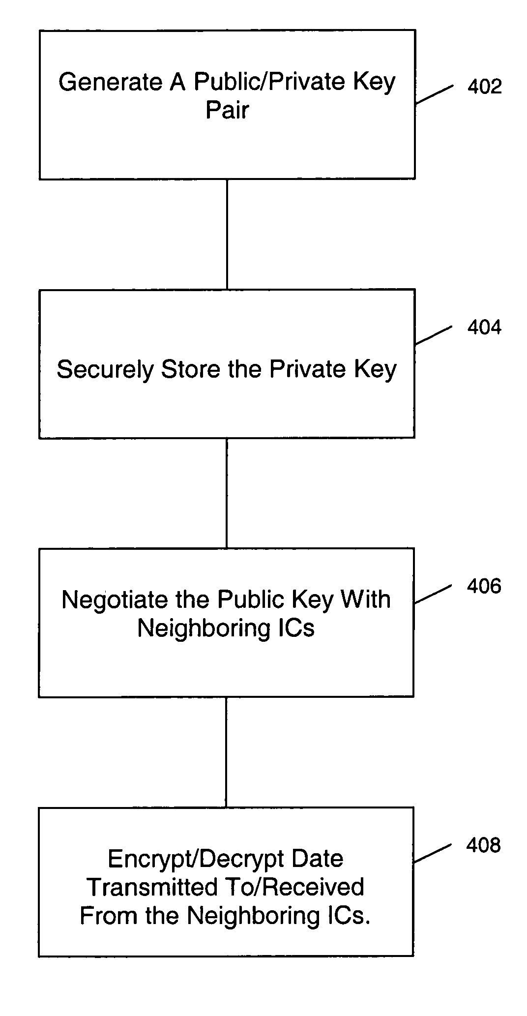
[0030] In one embodiment, the invention relates to a method and system for authenticating neighboring data processing ICs in a digital system / device and encrypting data communicated between the neighboring data processing ICs. The authentication and encryption are performed in each data processing IC. Each data processing IC authenticates its neighbor data processing IC and then encrypts data that is communicated between the two ICs. This way, the authentication and data encryption between the data processing ICs is performed in hardware at the physical layer. This approach also ensures that a software application runs on a trusted hardware without having to require another application to ensure its security boundary.

[0031]FIG. 3 is an exemplary block diagram of a typical digital system / device. The digital system / device may be a PC, a set-top box, a mobile phone, and the like. The data processing ICs may be located in one or more PCBs, and / or multi-chip modules. At power up, each d...


PUM


Abstract

A secure digital system including a number of ICs that exchange data among each other. Each of the ICs includes a key generator for generating a cipher key; a memory for securely storing the generated cipher key; an authenticating module for authenticating neighboring ICs of a respective IC; an encryption module for encrypting data communicated from the respective IC to the neighboring ICs; and a decryption module for decrypting data received from the neighboring ICs.

Description

CROSS-REFERENCE TO RELATED APPLICATIONS [0001] This patent application claims the benefit of the filing date of U.S. Provisional Patent Application Ser. No. 60 / 631,484, filed Nov. 29, 2004 and entitled “METHOD AND APPARATUS FOR SECURITY OVER MULTIPLE INTERFACES”; the entire contents of which are hereby expressly incorporated by reference.FIELD OF THE INVENTION [0002] This application relates to secure digital systems / devices and more specifically, to an integrated circuit chip secured at the hardware level. BACKGROUND OF THE INVENTION [0003] The proliferation of distributed computing networks has brought with it a greater need to secure the information that is transmitted through the networks. Moreover, with higher integration of electronic circuits on smaller Integrated Circuits (ICs), electronic components are increasingly capable of processing more complex data and performing more functions. ICs within the same digital system, for example, a Personal Computer (PC), a set-top box,...

Claims


Application Information

Patent Timeline
Patent Type & Authority Applications(United States)
IPC IPC(8): H04L9/00
CPCG06F21/72G06F2221/2129H04L9/0861H04L2209/56H04L9/0877H04L9/3297H04L9/0841
Inventor BUER, MARK L.FRANK, EDWARD H.
Owner AVAGO TECH INT SALES PTE LTD
Learn More