Adaptive-type sigma-delta a/d converter
a converter and adaptive technology, applied in the field of sigma-delta a/d converters, can solve the problems of deterioration of s/n ratio, increase in circuit complexity, etc., and achieve the effect of no increase in power consumption, extremely small increase in circuit size, and small number of additional circuit elements
- Summary
- Abstract
- Description
- Claims
- Application Information
AI Technical Summary
Benefits of technology
Problems solved by technology
Method used
Image
Examples
first embodiment
[0037]FIG. 3 is a circuit diagram showing the construction of the variable-signal-level D / A converter 205 according to the present invention. The variable-signal-level D / A converter 205 of FIG. 3 includes a charge-purpose reference potential source 301, charging / discharging changeover switches 302 through 305, a straight / cross switching unit 306, capacitor selecting switches 307 through 312, and capacitors 313 through 315.
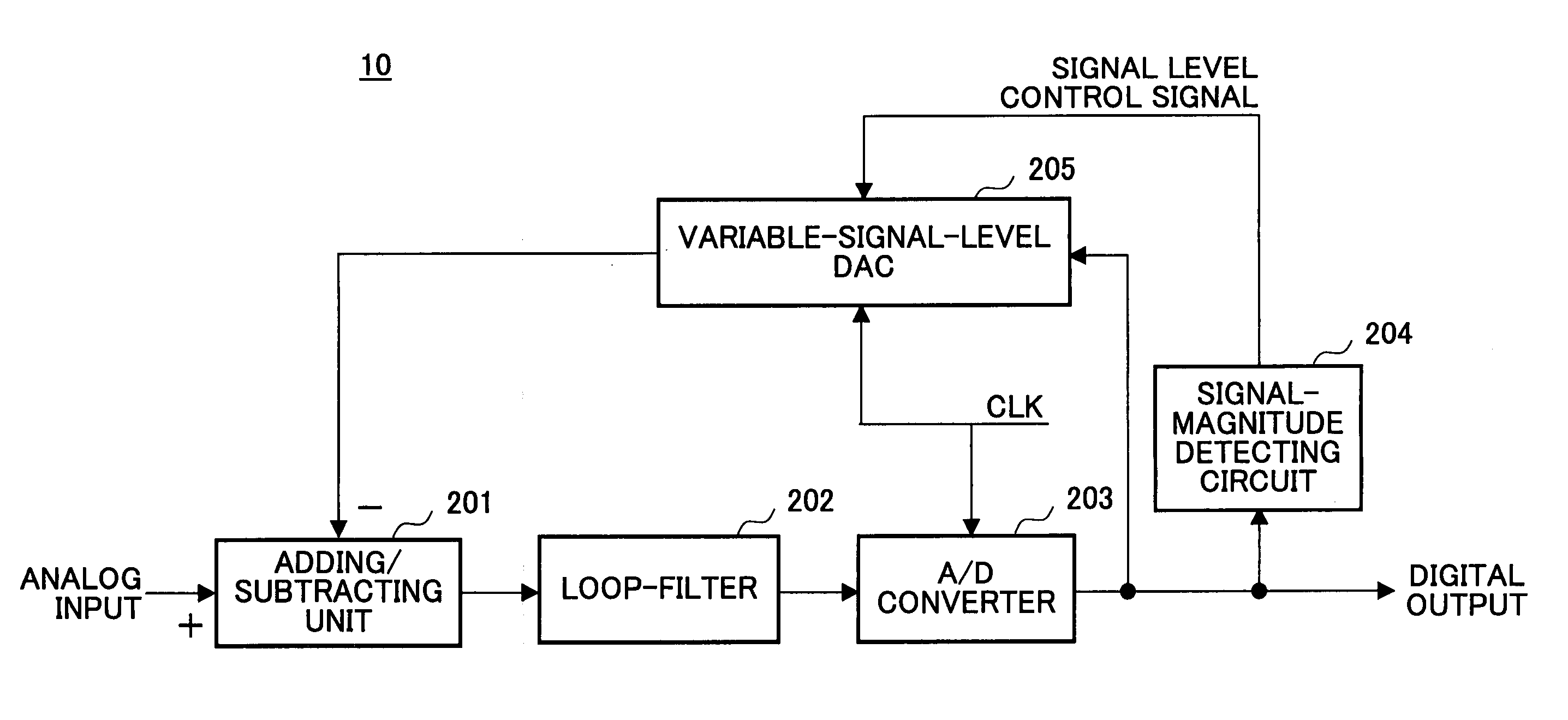
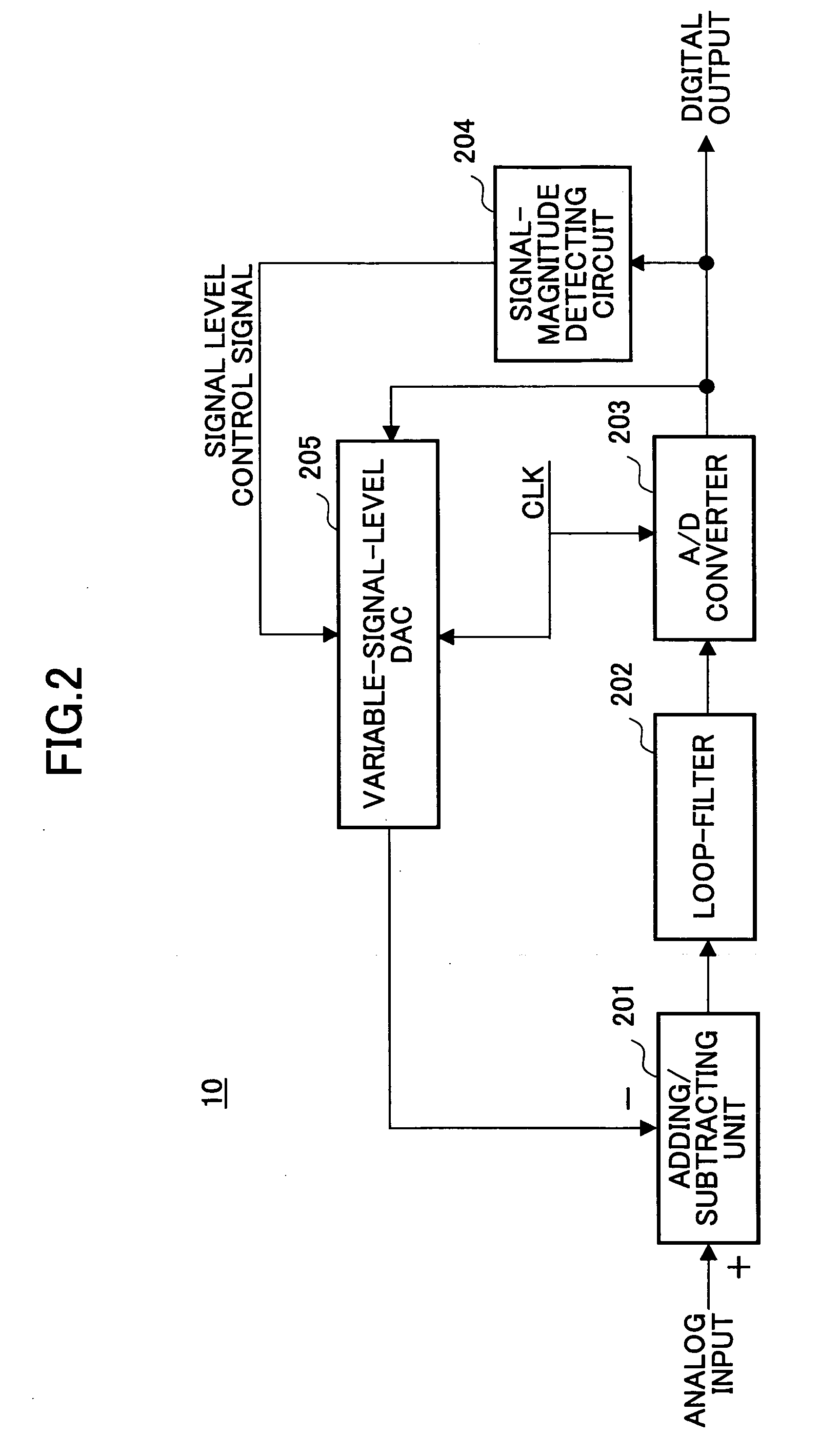
[0038] The on / off states of the capacitor selecting switches 307 through 312 are controlled based on control signals responsive to the detected magnitude that is supplied from the signal-magnitude detecting circuit 204. To be specific, the number of the on-state switches increases as the detected magnitude rises, and decreases as the detected magnitude falls.
[0039] During the period in which the clock signal CLK is LOW, the switches 302 and 303 are closed. As a result, electric charge from the charge-purpose reference potential source 301 is supplied to the capaci...
second embodiment
[0043]FIG. 4 is a circuit diagram showing the construction of the variable-signal-level D / A converter 205. The variable-signal-level D / A converter 205 shown in FIG. 4 includes a charge-purpose reference potential source 401, charging / discharging changeover switches 402 through 405, a straight / cross switching unit 406, capacitor selecting switches 407 through 418, and capacitors 419 through 424.
[0044] The on / off states of the capacitor selecting switches 407 through 418 are controlled based on control signals responsive to the detected magnitude that is supplied from the signal-magnitude detecting circuit 204. To be specific, the number of the on-state switches increases as the detected magnitude rises, and decreases as the detected magnitude falls.
[0045] During the period in which the clock signal CLK is LOW, the switches 402 and 403 are positioned as illustrated by solid lines, and the switches 404 and 405 are positioned as illustrated by doted lines. As a result, electric charge ...
PUM
 Abstract
Description
Claims
Application Information
 - R&D
- Intellectual Property
- Life Sciences
- Materials
- Tech Scout
- Unparalleled Data Quality
- Higher Quality Content
- 60% Fewer Hallucinations
Browse by: Latest US Patents, China's latest patents, Technical Efficacy Thesaurus, Application Domain, Technology Topic, Popular Technical Reports.
© 2025 PatSnap. All rights reserved.Legal|Privacy policy|Modern Slavery Act Transparency Statement|Sitemap|About US| Contact US: help@patsnap.com


