
Utility mapping and data distribution system and method

a mapping and data technology, applied in wave based measurement systems, instruments, reradiation, etc., can solve the problems of utility detection problems, physical access to utilities, and utility detection costs, and achieve the effect of improving the accuracy of utility detection

Inactive Publication Date: 2006-04-20
VERMEER MFG CO
View PDF39 Cites 172 Cited by
  • Summary
  • Abstract
  • Description
  • Claims
  • Application Information

AI Technical Summary

Benefits of technology

This approach significantly enhances the accuracy of underground utility detection and mapping, providing reliable data for safer and more efficient subsurface operations by overcoming limitations of single-sensor technologies like GPR, especially in conductive soils.

Problems solved by technology

Active systems are problematic for various reasons, such as the difficulty and cost of physically accessing the utility and difficulty in sensing non-conductive utilities.
However, GPR has problems detecting utilities in certain soil types and conditions that limit GPR's use in many areas of the United States and the world, such as much of southwest United States (e.g., Arizona).
However, the One-Call system is not particularly reliable, as only a certain percentage of the utilities are recorded, and those that are recorded may have suspect or imprecise location data.
As such, currently-existing location data for buried utilities is incomplete and often questionable in terms of reliability.

Method used


Image

  • Utility mapping and data distribution system and method
  • Utility mapping and data distribution system and method
  • Utility mapping and data distribution system and method

Examples


Embodiment Construction

[0049] In the following description of the illustrated embodiments, references are made to the accompanying drawings which form a part hereof, and in which is shown by way of illustration, various embodiments in which the invention may be practiced. It is to be understood that other embodiments may be utilized, and structural and functional changes may be made without departing from the scope of the present invention.

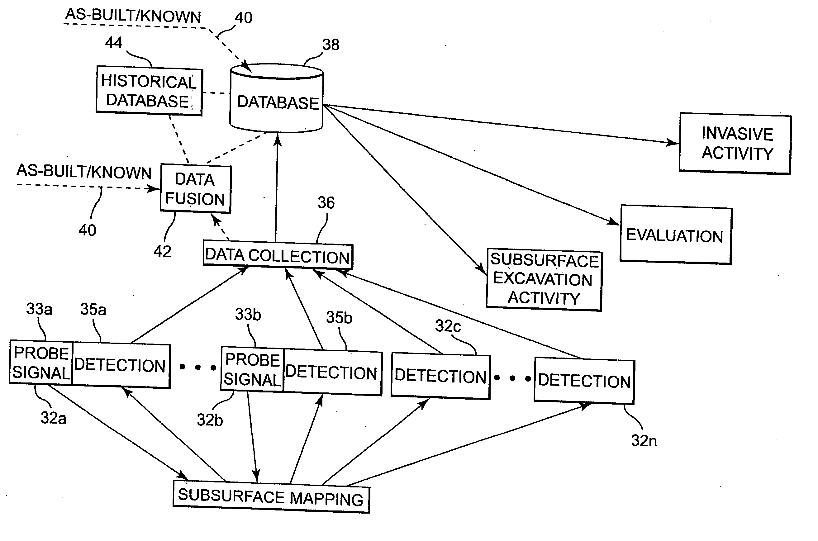
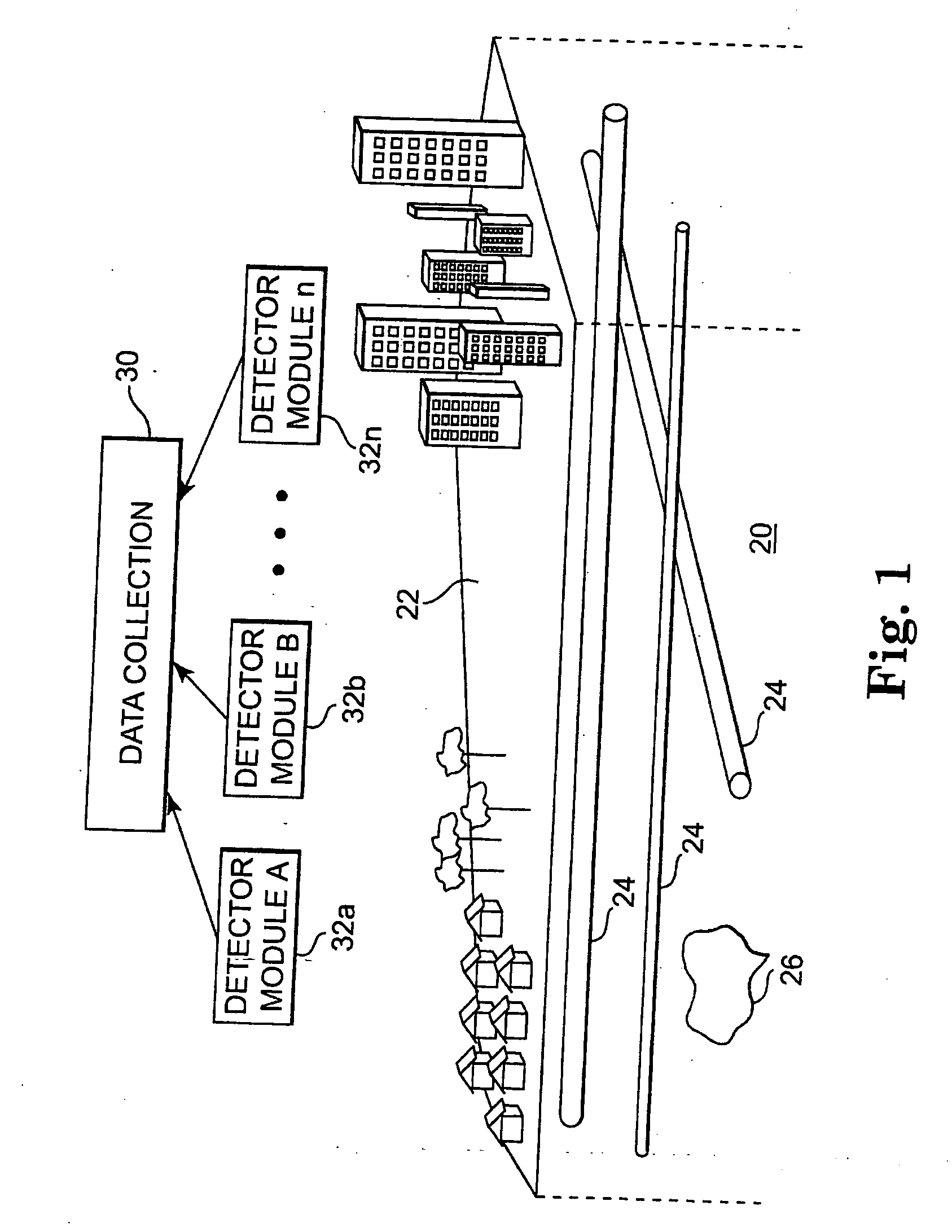
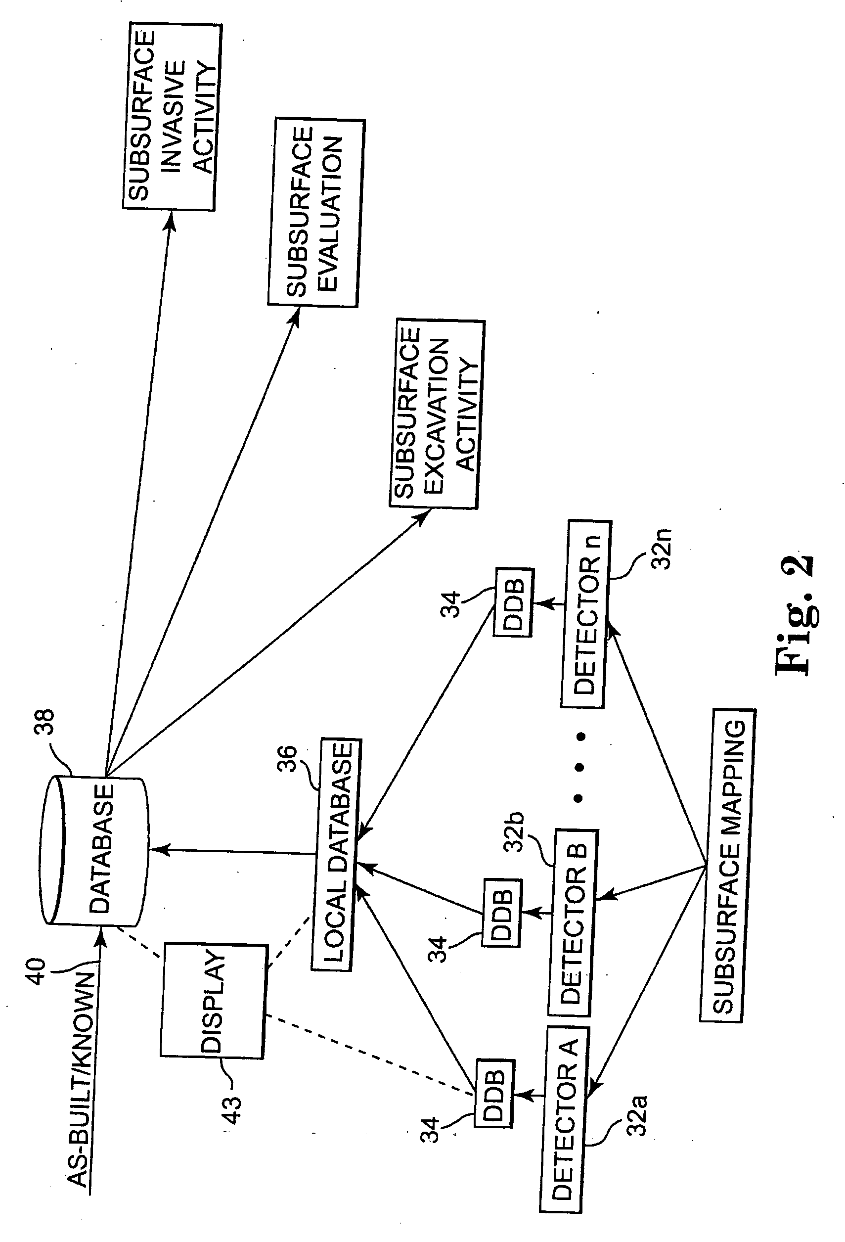
[0050] According to an embodiment of the present invention, location data for an existing or new installation site is acquired using at least one, and generally several, utility detectors. One or more of the utility detectors may be of type that generates a probe signal, transmits the probe signal into the subsurface of interest, and detects a response signal from the subsurface. The response signal may be a naturally occurring reflection signal or a signal produced by a device situated within the subsurface, such as by a device mounted to an existing or newly installe...


PUM


Abstract

A system and method of mapping underground utilities and other subsurface objects involves one or more of acquiring utility location data using a number of different detectors and sensors, processing the multiple detector / sensor output data to produce mapping data, storing the mapping data in a database, and providing access to and use of the stored mapping data by subscribing users on a usage fee basis.

Description

RELATED APPLICATIONS [0001] This application claims priority to provisional application U.S. Ser. No. 60 / 211,431, filed Jun. 14, 2000, and is a divisional of U.S. Ser. No. 10 / 867,885, filed Jun. 14, 2004, to issue as U.S. Pat. No. 6,975,942 on Dec. 13, 2005, which is a divisional of U.S. Ser. No. 09 / 881,656, filed on Jun. 14, 2001 which issued as U.S. Pat. No. 6,751,553 on Jun. 15, 2004, which are hereby incorporated by reference in their respective entireties.FIELD OF THE INVENTION [0002] The present invention relates generally to the field of underground utility and object detection, and, more particularly, to one or more of detecting buried utility and subsurface objects, mapping such utilities and objects, and electronically distributing mapping data to subscribing users. Background of the Invention [0003] Various techniques have been developed to locate and map underground utilities and other manmade subsurface structures. Present utility mapping practices take two basic forms:...

Claims


Application Information

Patent Timeline
Patent Type & Authority Applications(United States)
IPC IPC(8): G06F19/00G01V11/00
CPCG01V1/00G01V11/002G01V2210/6163G01V11/00
Inventor YOUNG, GARY NEALALFT, KEVIN L.
Owner VERMEER MFG CO
Learn More