Apparatus and method for optical switching at an optical switch fabric

a technology of optical switch fabric and optical switch, applied in the field of optical crossbar switch, can solve the problems of reducing efficiency, current telecommunications network not meeting these requirements, electrical and electro-optical switching routers are limited in switching speeds, etc., and achieve the effect of increasing the router/switch capacity and high scalabl

Inactive Publication Date: 2006-04-20
UNWIRED BROADBAND INC
View PDF41 Cites 16 Cited by
  • Summary
  • Abstract
  • Description
  • Claims
  • Application Information

AI Technical Summary

Benefits of technology

[0010] The present invention provides a non-blocking optical routing system and method that substantially eliminates or reduces disadvantages and problems associated with previously developed optical routing systems and methods.
[0013] Embodiments of the present invention provide an important technical advantage with respect to previous optical routing systems and methods by providing non-blocking routing of optical data packets without increasing the router / switch capacity beyond the capacity that is being served.
[0014] Embodiments of the present invention provide another important technical advantage by providing an optical cross-bar switch fabric that includes a unique switch path from each input link to each output link, to ensure that no blocking or congestion will occur in the switch fabric.
[0015] Embodiments of the present invention provide yet another important technical advantage by providing the ability to broadcast and multicast data packets without blocking or contention.
[0016] Embodiments of the present invention provide yet another important technical advantage providing a scalable switch fabric architecture that can accommodate the ability to send a greater number of wavelengths across a single optical link.
[0017] Embodiments of the present invention provide yet another important technical advantage by being highly scalable.

Problems solved by technology

Current telecommunications networks fail to meet these requirements.
Existing electrical and electro-optical switching routers are limited in the switching speeds that are attained and the data capacity that can be processed between switches in a non-blocking manner.
However, while the overall speed and capacity will exceed one Gigabit, this aggregation will not result in full 100 Gigabit per second speed and capacity, resulting in a decreased efficiency (less than full realization of the switching capability).
Furthermore, aggregation increases costs due to the increased number of routers and increases complexity due to interconnect and routing issues.
In addition to the issues surrounding data routing speed, electronic telecommunication routing systems all face difficult transference issues when interfacing with optical data packets.
However, this technique has its own limitations including control complexity (it is difficult to control the multiple routers operating in parallel).
In any of these techniques involving multiple routers to increase the processing speed, a single control machine must arbitrate among the many multiple machines, which increases control complexity, cost and ultimately uses an electronic control machine that is limited by electronic processing speeds.
This configuration has a number of limitations.
However, due to inefficiencies in this network configuration (as described above), the full potential of 2.5 Terabits cannot be achieved without a tremendous increase in the size of the edge routers 22.
To increase the capacity between routers in a non-blocking manner, the individual routers would need to be increased in capacity tremendously, which increases cost and further exacerbates the under-utilization problems already existing in the network.

Method used


Image

  • Apparatus and method for optical switching at an optical switch fabric
  • Apparatus and method for optical switching at an optical switch fabric
  • Apparatus and method for optical switching at an optical switch fabric

Examples


Embodiment Construction

[0027] Preferred embodiments of the present invention are illustrated in the FIGUREs, like numerals being used to refer to like and corresponding parts of the various drawings.

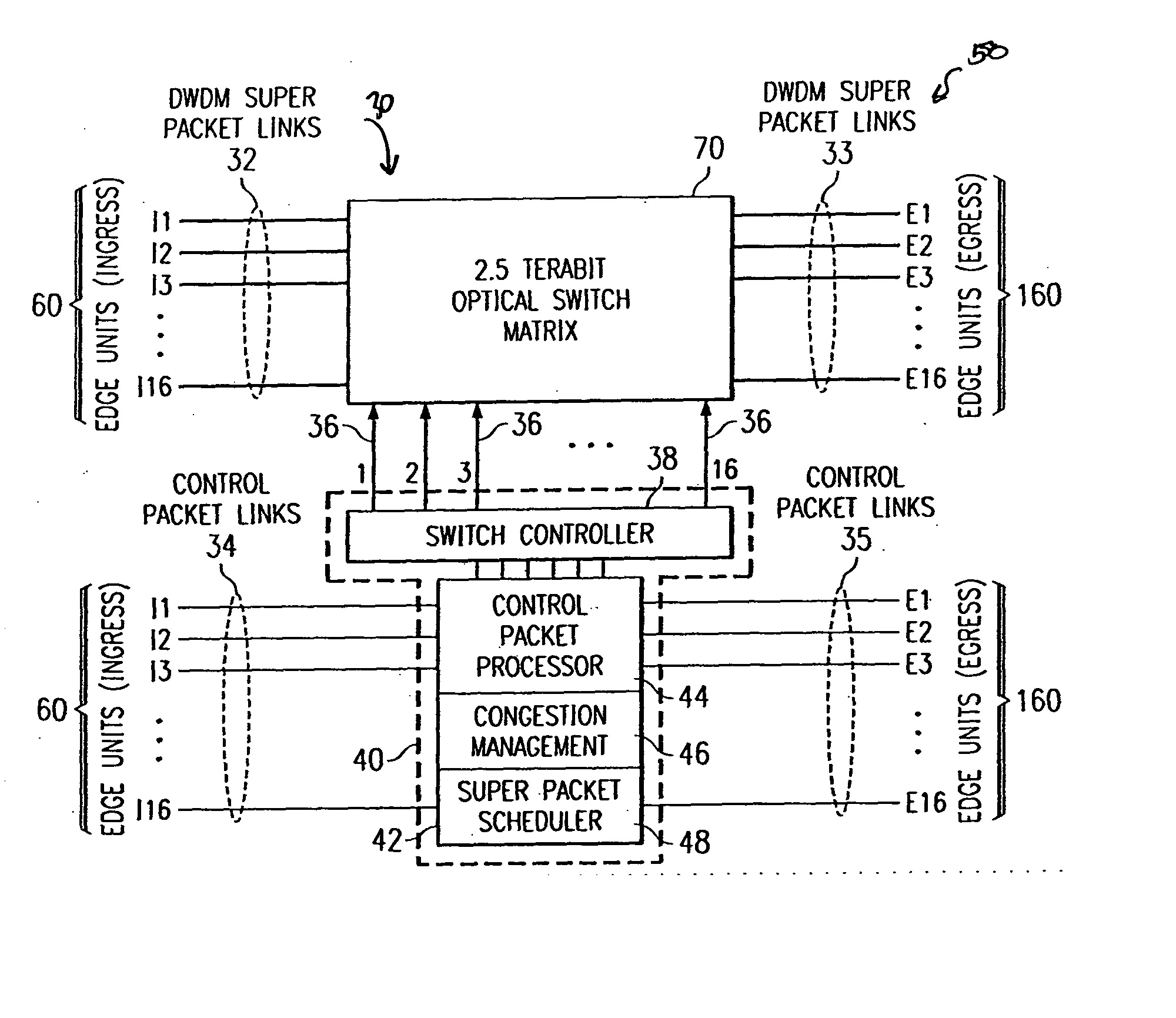
[0028] The present invention provides an optical switch architecture that provides full, non-blocking interconnectivity without increasing the router / switch capacity beyond that required to service the data capacity coming into the router / switch from the network communities being serviced. The present invention provides routing for fixed and variable length optical data packets of varying types (including Internet Protocol (IP), data, voice, TDM, ATM, voice over data, etc.) at speeds from sub-Terabit per second (Tbps) to significantly in excess of Petabit per second (Pbps). The present invention utilizes a unique, non-blocking optical switching architecture to obtain these benefits in speed and interconnected capacity.

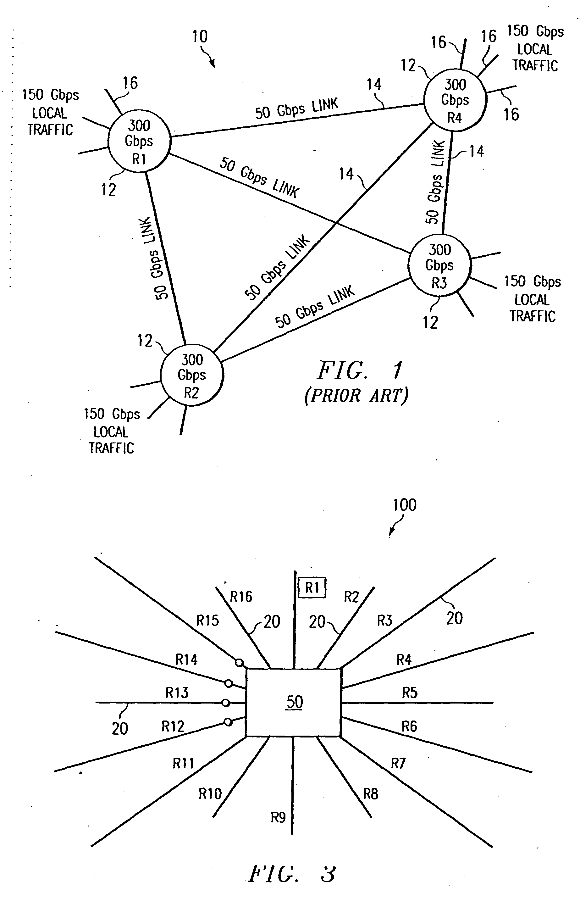
[0029]FIG. 3 shows an optical network 100 including a number of data lines 20 (or “data lin...


PUM


Abstract

Embodiments of the present invention provide a system and method for providing non-blocking routing of optical data through an optical switch fabric. The optical switch fabric can include an optical switching matrix with a plurality of inputs intersecting with a plurality of outputs. A path switch can be located at each intersection that is operable to switch data arriving on an input to a particular output. The path switches can be configurable to create a plurality of unique paths through the optical switching matrix to allow routing in a non-blocking manner. Another aspect of the present invention can provide a system and method for providing non-blocking routing through an optical cross-bar switch. The optical cross-bar switch includes a plurality of input links, a plurality of output links and a plurality of switching elements. Each switching element can include a plurality of path switches connecting each of the input links to at least one of the output links and the plurality of switching elements can be configured to create a plurality of unique paths through the optical cross-bar switch.

Description

RELATED INFORMATION [0001] This application claims priority to and is a continuation in part of U.S. patent application Ser. No. 09 / 698,666, entitled “Non-Blocking, Scalable Optical Router Architecture and Method for Routing Optical Traffic” filed on Oct. 27, 2000, which is hereby fully incorporated by reference.TECHNICAL FIELD OF THE INVENTION [0002] The present invention relates generally to telecommunications systems and methods, and more particularly, to an optical cross-bar switch having an architecture to optimize the switching of optical data packets. BACKGROUND OF THE INVENTION [0003] The emergence of the Internet and the reliance by businesses and consumers on the transfer of data in an increasing number of daily activities requires telecommunications networks and components that can deliver ever increasing amounts of data at faster speeds with higher quality levels. Current telecommunications networks fail to meet these requirements. [0004] Existing electrical and electro-...

Claims


Application Information

Patent Timeline
IPC IPC(8): G02B6/26H04L12/56H04Q11/00
CPCH04L45/00H04L45/302H04L45/62H04L47/10H04L47/2433H04L47/2441H04L47/33H04L49/101H04L49/1523H04L49/205H04L49/254H04L49/3009H04L49/3081H04L49/357H04L49/503H04L2012/5662H04Q11/0005H04Q11/0062H04Q11/0066H04Q11/0071H04Q2011/0024H04Q2011/0033H04Q2011/0039H04Q2011/005H04Q2011/0073H04Q2011/0079H04Q2011/0084
Inventor TAMIL, LAKSHMAN S.
Owner UNWIRED BROADBAND INC
Why Eureka
Try Eureka