
Sensor infrastructure

Active Publication Date: 2006-04-13
METIS DESIGN CORP
View PDF39 Cites 27 Cited by
  • Summary
  • Abstract
  • Description
  • Claims
  • Application Information

AI Technical Summary

Benefits of technology

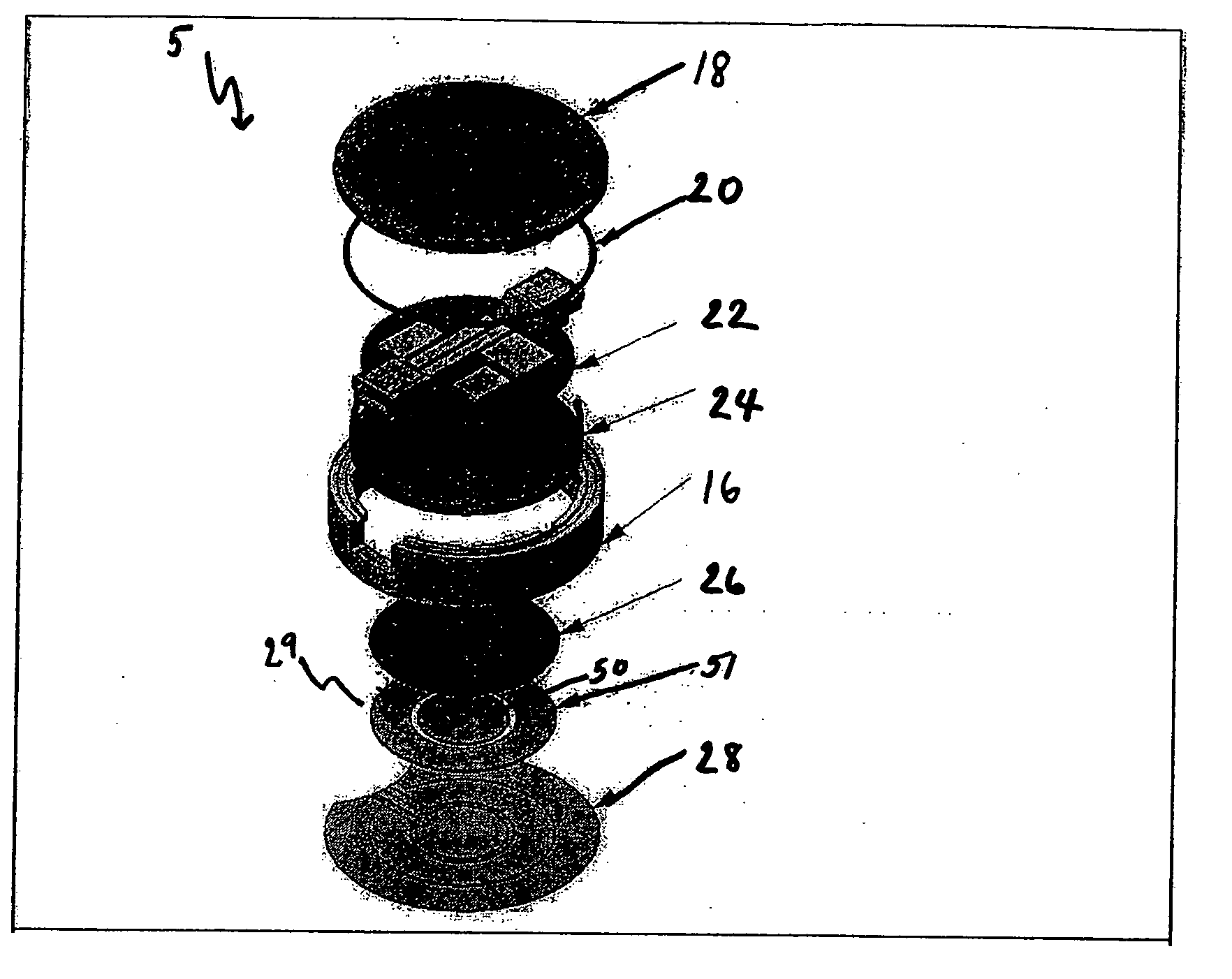
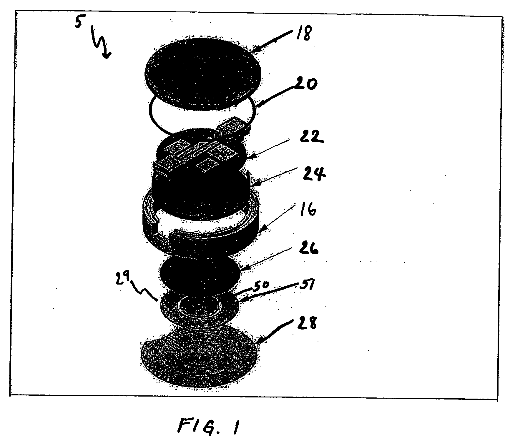
[0007] In order to practically attain the full economic and design benefits of SHM, several components that amount to sensor infrastructure are integrated into a small package, and an architecture is developed. The components can include a microprocessor to command testing, a function generator to excite actuators, an amplifier to increase signal strength, an acquisition chip to collect data, power, connectors, a communication standard, shielding from electric and magnetic interference, and casing to protect and package the components.
[0008] The invention provides one or more of the following capabilities. The damage detection infrastructure can be mass-produced at a low cost, and customized for any application in software. The infrastructure can be broadly defused in aerospace, automotive, naval and civil applications, or any field in which a single sensor or a distributed network of sensors is required to collect data. The infrastructure can be integrated into ageing structures or integrated into newly designed structures. The invention can enable the elimination of scheduled inspections. Structural design can be improved with increased reliability and reduced life-cycle costs. Embodiments of the invention can be constructed without the use of solder and exposed wires. Fewer sensors can accomplish detection without limiting the range over which detecting is desired. Embodiments of the invention can be implemented as a continuously monitoring system, which can require less human intervention. Other capabilities will be apparent upon a review of the Figures and Detailed Description that follows.

Problems solved by technology

Known methods of laboratory non-destructive structural testing (NDT) methods, such as X-ray detection and C-scans, are impractical for service inspection of built-up structures due to the size and complexity of their infrastructure.

Method used


Image

  • Sensor infrastructure
  • Sensor infrastructure
  • Sensor infrastructure

Examples


Embodiment Construction

[0019] The features and other details of the invention will now be more particularly described. It will be understood that particular embodiments described herein are shown by way of illustration and not as limitations of the invention. The principal features of this invention can be employed in various embodiments without departing from the scope of the invention.

[0020] Embodiments of the invention are directed to concentrically positioned sensors and actuators. Embodiments of the invention can be directed to a piezoelectric-based sensor and actuator for use in facilitating damage detection, non-destructive testing (“NDT”) and structural health monitoring (“SHM”) using a variety of sensors and sensing methods. Embodiments of the invention can include damage detection systems employing one or more than one piezoelectric damage detector. Embodiments of the invention can be directed to an infrastructure for use in monitoring a structure. Embodiments of the invention relate to a colle...


PUM


Abstract

A device for use in detecting an event in a structure comprises a sensor encapsulation, the encapsulation containing a sensor, an actuator positioned substantially in-plane to the sensor within the housing and a printed circuit board in communication with at least one of the sensor and the actuator. the printed circuit board includes a microprocessor constructed and arranged to collect data from at least one of the sensor and the actuator, a signal generator constructed and arranged to provide excitation to at least one of the sensor and the actuator, and an amplifier to condition the excitation.

Description

RELATED APPLICATIONS [0001] This application claims the benefit of priority to U.S. Provisional Application Ser. No. 60 / 616,748, filed on Oct. 7, 2004 and U.S. Provisional Application Ser. No. 60 / 616,705, filed on Oct. 7, 2004, each of which is herein incorporated by reference in its entirety.FIELD OF THE INVENTION [0002] The invention generally relates to the field of sensing, monitoring, damage detection and structural health monitoring systems defused in aerospace, automotive, naval, civil or other applications. BACKGROUND OF THE INVENTION [0003] Known methods of laboratory non-destructive structural testing (NDT) methods, such as X-ray detection and C-scans, are impractical for service inspection of built-up structures due to the size and complexity of their infrastructure. Structural Health Monitoring (SHM) involves the incorporation of non-destructive test methods into a structure to provide continuous remote monitoring for damage. SHM systems are systems with the ability to d...

Claims


Application Information

Patent Timeline
IPC IPC(8): G01B5/00
CPCG01B5/30G01L1/16G01M5/0033G01M5/0075G01N29/045G01N29/12G01N29/2475G01N29/2481G01N2291/0258G01N2291/02827G01N2291/02845G01N2291/0422G01N2291/0427G01N2291/106G01N2291/2694
Inventor KESSLER, SETH S.JUGENHEIMER, KRISTIN A.SIZE, AARON B.
Owner METIS DESIGN CORP
Learn More