
Disc drive with improved resistance against mechanical shocks

a disc drive and mechanical shock technology, applied in the direction of instruments, recording information storage, disposition/mounting of heads, etc., can solve the problems of reducing the suspension damping rate to increase and affecting the effect of the shock immunity level

Inactive Publication Date: 2006-04-06
KONINKLIJKE PHILIPS ELECTRONICS NV
View PDF5 Cites 8 Cited by
  • Summary
  • Abstract
  • Description
  • Claims
  • Application Information

AI Technical Summary

Benefits of technology

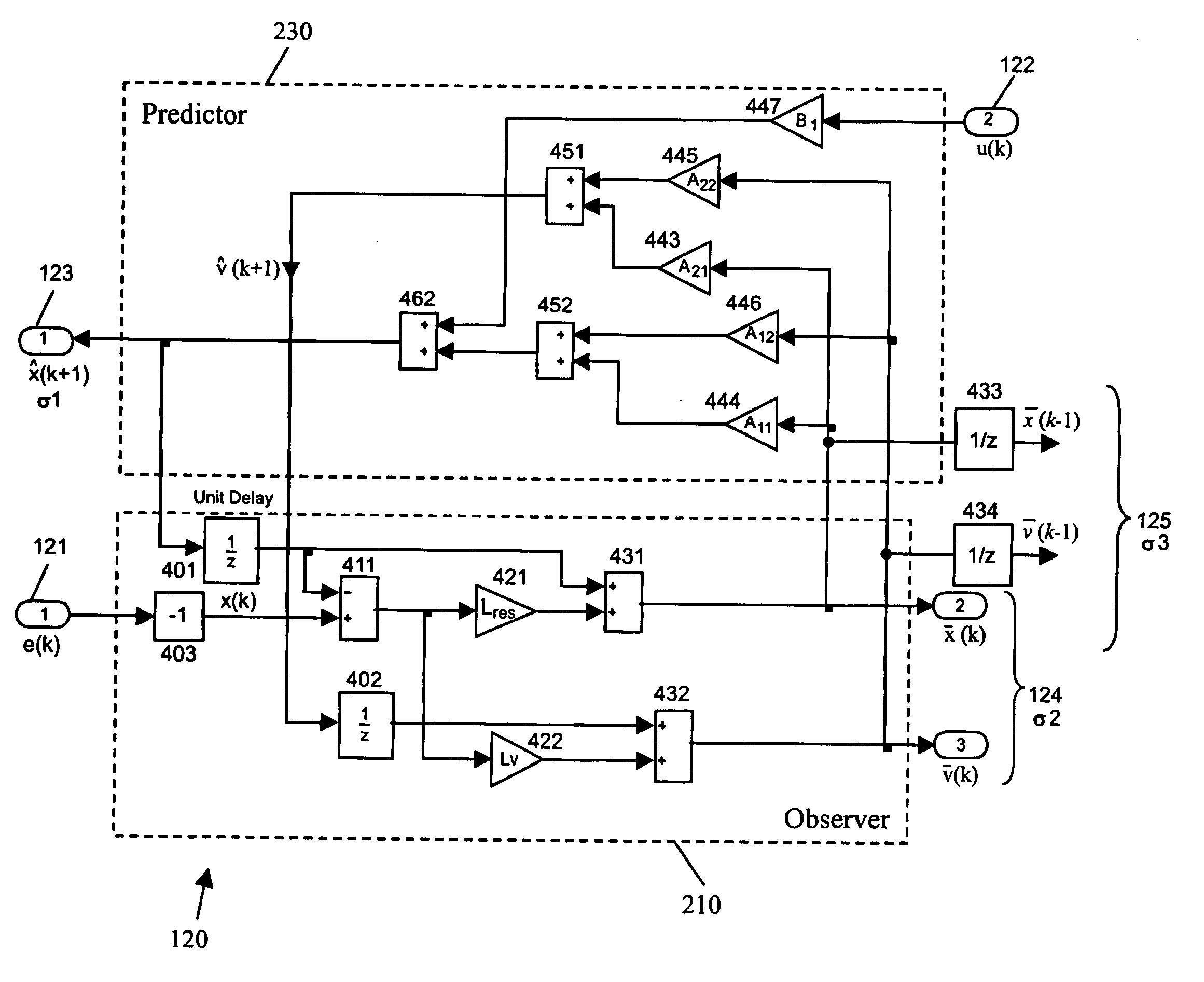
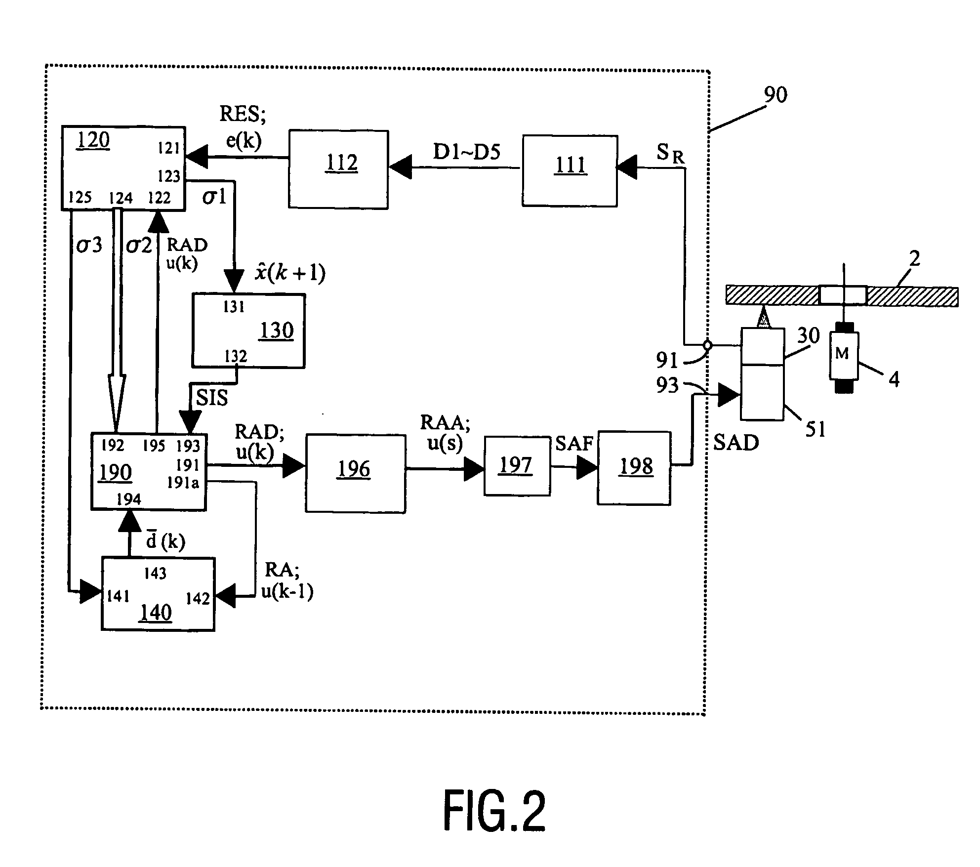
[0024] According to a specific aspect of the present invention, a shock is detected on the basis of an output signal of a state estimator. An important advantage is the fact that the state estimator is able to detect shocks early, so that the response time can be reduced.

Problems solved by technology

Position errors may, in practice, be caused by different types of disturbances.
A problem in this respect is that adequately handling shocks requires a different control characteristic than normal operating conditions.
However, the suspension design depends not only on the drive operational shock sensitivity but also on the suspension performance and dynamic range under all circumstances during operating, handling and transportation, and material cost, mechanical design tolerances etc.
The lowering of the suspension damping rate to increase the shock immunity level is very much limited from the system point of view.
Further more, the robustness to external shock by increasing the servo gain is also limited by the system stability requirements.
Utilizing a shock sensor is a direct method for accurate shock detection, but this will increase the product cost.
Also, the system requirements of stability will limit the shock performance improvement.
One disadvantage of this method is that it relies on data written on the disc; it is not applicable in the case of blank discs.
Another disadvantage is that this method requires complicated circuitry, inter alia for detecting upper peaks and lower peaks, for filtering in order to detect upper envelope and lower envelope, for analysing these envelopes, and for storing signals in a memory.
Increasing the gain of a PID controller only has a limited result.

Method used


Image

  • Disc drive with improved resistance against mechanical shocks
  • Disc drive with improved resistance against mechanical shocks
  • Disc drive with improved resistance against mechanical shocks

Examples


example

[0100] As an example, an experimental simulation has been conducted on a DVD player. FIG. 7 shows the Bode plot of the radial actuator for the drive. The initial value of the estimator gains are decided by the LQR method and the final gain values for the DVD player drive radial actuator are decided on pole placement by trial and error as:

Lres=1.3e4; Lv=1.7241e6

[0101] The linear controller gains for the radial actuator during tracking for the DVD player drive are:

gres=1.e2; gv=1.6e4; ε=600

where the control gain e of SMC controller is determined such that the whole system gives about the same crossover frequency as that of the original PID controller, that is 2.2 kHz, when the radial error is within the boundary area. Here, a boundary of 1000 is used, this is corresponding to a threshold value of 20% peak off-track (⅕ of track pitch value). When the system is operating outside the boundary layer, like when experiencing a shock / impact, and the radial error intends to become to mor...


PUM

PropertyMeasurementUnit
frequencyaaaaaaaaaa
thresholdaaaaaaaaaa
crossover frequencyaaaaaaaaaa

Abstract

A disc drive apparatus (1) comprises; a) actuator means (50) for controlling the positioning of an element (34) of a scanning means; b) error signal calculating means (111, 112) for receiving a read signal (SR) and generating at least one error (RES; e(k)); c) a state estimator (120) for receiving said error and for outputting derived signals (s1, s2, s3); d) shock detector means (130) for generating a shock indication signal (SIS); e) actuator control signal generator means (190) designed to perform sliding mode control (SMC), having at least one variable control parameter, for generating an actuator control signal (RAD; u(k)) on the basis of a second one (s2) of said derived signals; f) the actuator control signal generator means setting a first value for said variable control parameter during normal operation, and setting a second value for said variable control parameter when said shock indication signal indicates the occurrence of a shock.

Description

FIELD OF THE INVENTION [0001] The present invention relates in general to an optical disc drive apparatus for writing / reading information into / from an optical storage disc. BACKGROUND OF THE INVENTION [0002] As is commonly known, an optical storage disc comprises at least one track, either in the form of a continuous spiral or in the form of multiple concentric circles, of storage space where information may be stored in the form of a data pattern. Optical discs may be read-only type, where information is recorded during manufacturing, which information can only be read by a user. The optical storage disc may also be a writeable type, where information may be stored by a user. For writing information in the storage space of the optical storage disc, or for reading information from the disc, an optical disc drive comprises, on the one hand, rotating means for receiving and rotating an optical disc, and on the other hand optical means for generating an optical beam, typically a laser ...

Claims


Application Information

Patent Timeline
Patent Type & Authority Applications(United States)
IPC IPC(8): G11B7/00G11B7/09
CPCG11B7/0946G11B7/0925
Inventor ZHOU, YU
Owner KONINKLIJKE PHILIPS ELECTRONICS NV
Learn More