
Barrier layer and fabrication method thereof

a barrier layer and fabrication method technology, applied in the direction of semiconductor devices, semiconductor/solid-state device details, electrical devices, etc., can solve the problems of overhead and overhead problem becoming wors

Inactive Publication Date: 2006-03-30
TAIWAN SEMICON MFG CO LTD
View PDF9 Cites 3 Cited by
  • Summary
  • Abstract
  • Description
  • Claims
  • Application Information

AI Technical Summary

Benefits of technology

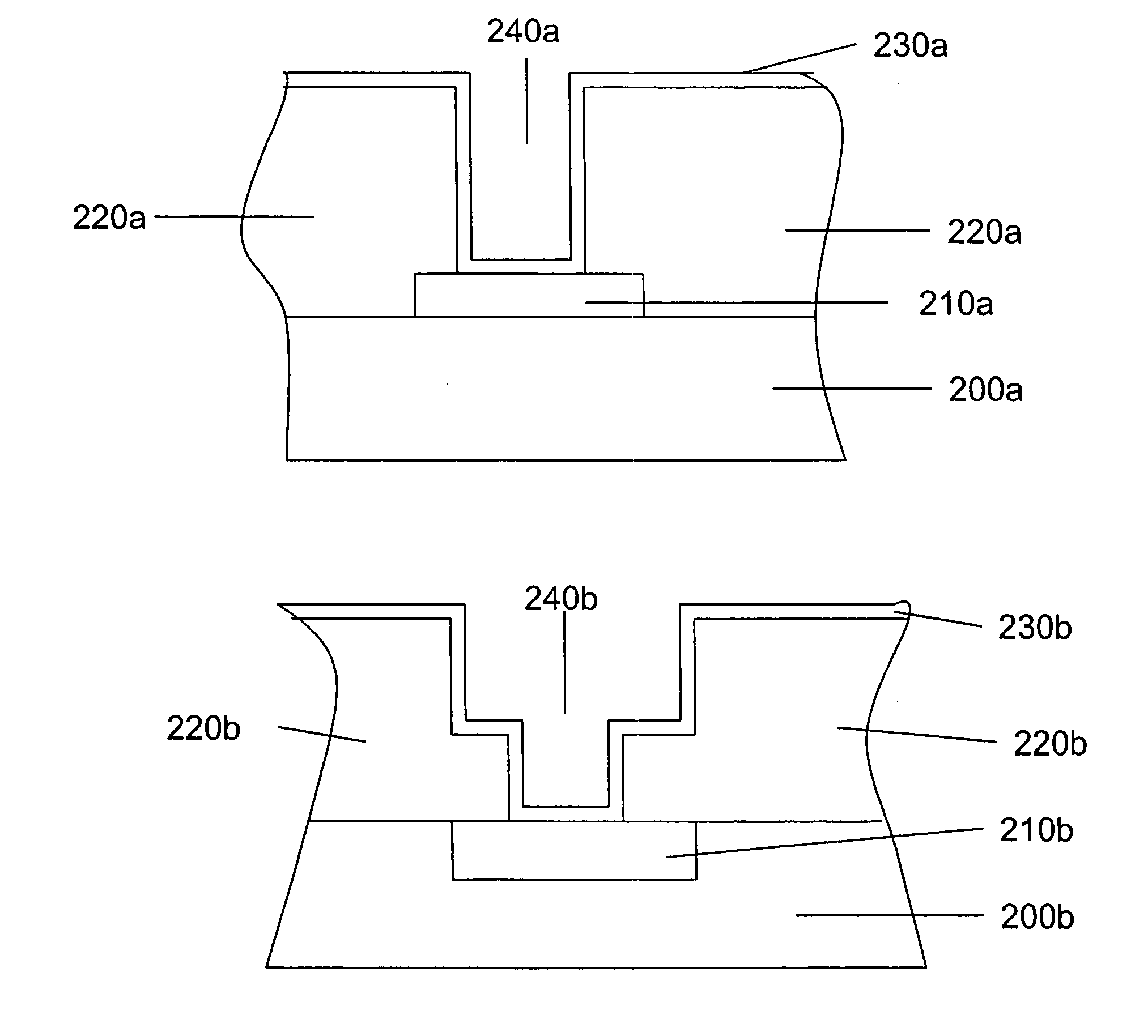
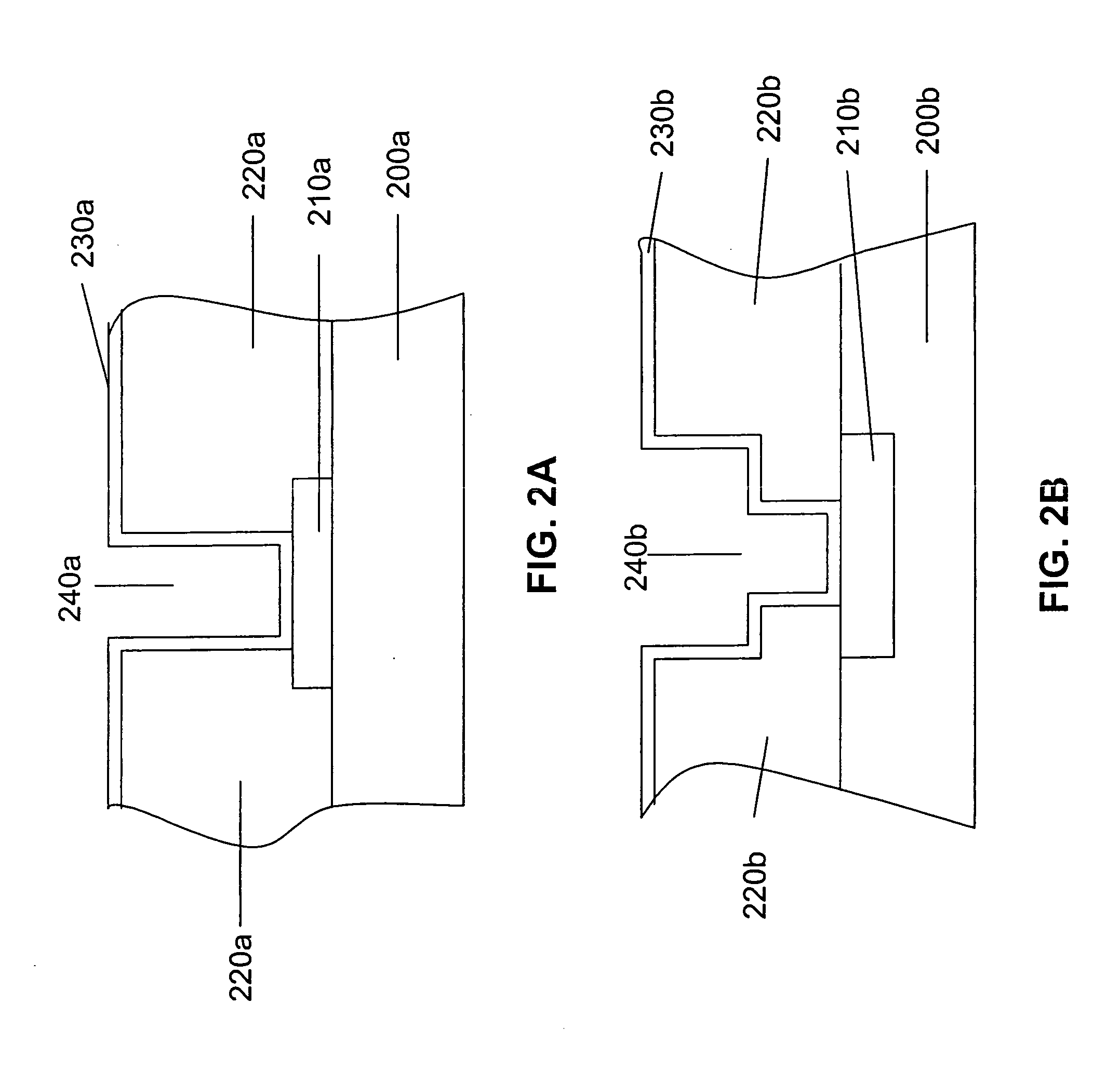
[0033] Under a high working pressure, the barrier layer formed by the exemplary methods is substantially conformal over the via or contact hole. Accordingly, the subsequent metal deposition process completely fills the metal layer in the via or contact hole without forming pin hole therein.

Problems solved by technology

In a worse case, a non-conformal barrier layer results in an overhead issue at the top of the via or contact hole.
The overhead issue becomes worse when the scale of the contact or via hole shrinks.

Method used


Image

  • Barrier layer and fabrication method thereof
  • Barrier layer and fabrication method thereof
  • Barrier layer and fabrication method thereof

Examples


Embodiment Construction

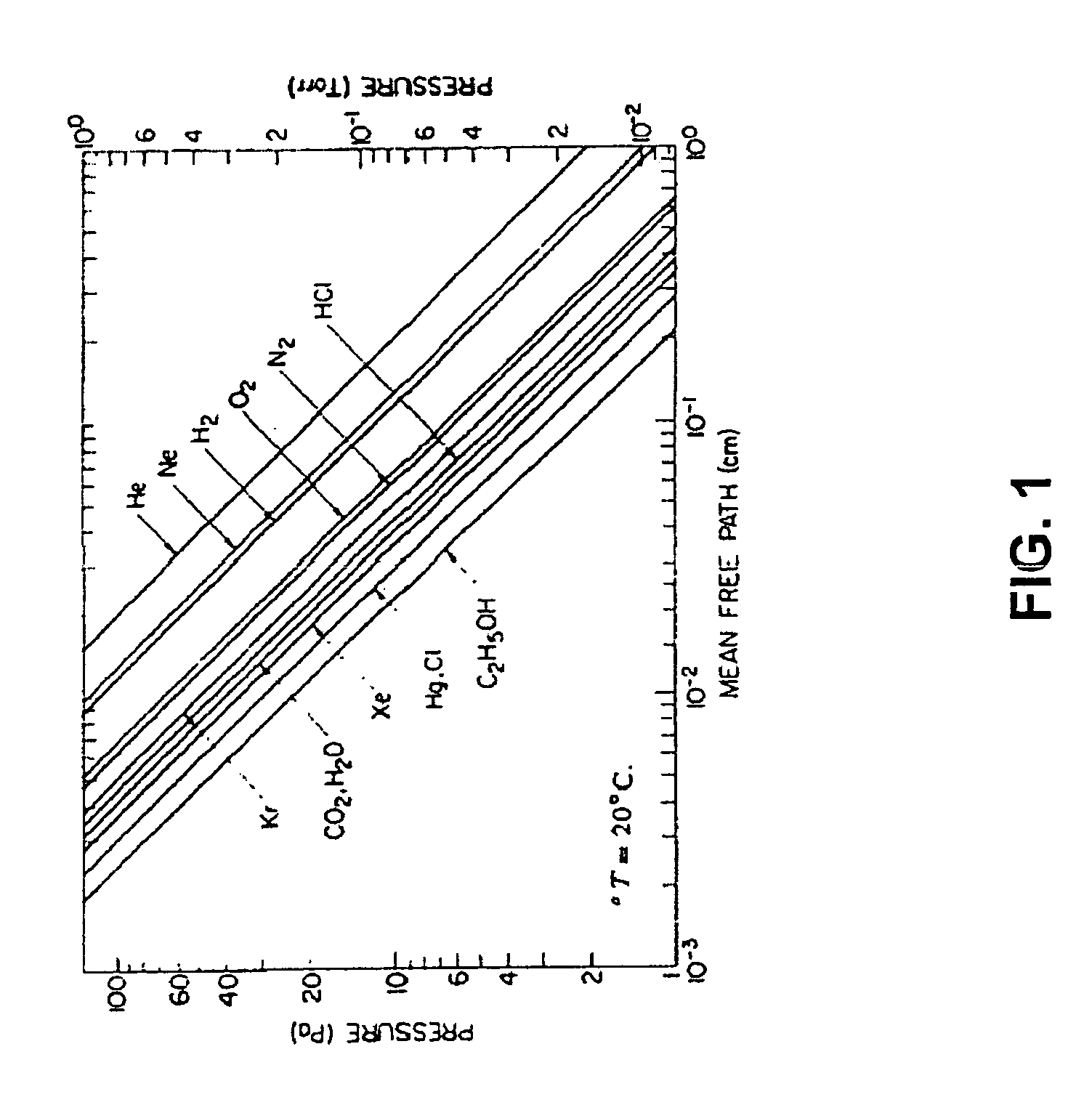
[0016]FIG. 1 is a drawing showing relationships between pressure and mean free path for different reaction gases.

[0017] Referring to FIG. 1, the drawing shows linear relationships between the pressure and the mean free path of different reaction gases. The relationships can be shown by the equation (1) as follows: L=12⁢(πδ2)=0.707δ⁢ ⁢n≈2.331×10⁻²⁰⁢TP⁢ ⁢δ2(1)

[0018] wherein L represents mean free path; δ represents the molecular diameter of the background gas atoms; n represents number density (atoms / cm3) of the background gas; T represents temperature; and P represents pressure.

[0019] From equation (1), the higher the pressure, the shorter the mean free path of atoms. Atoms sputtered by Physical Vapor deposition (PVD) with a reaction gas such as nitrogen or argon are disposed on the via or contact hole structure. With kinetic energy, the atoms move along the via or contact hole profile. The atoms on the sidewalls of the via or contact hole profile tend to move out from the sidewal...


PUM


Abstract

A barrier layer and a fabrication thereof are disclosed. The barrier layer comprises at least one barrier material selected from the group consisting of Ta, W, Ti, Ru, Zr, Hf, V, Nb, Cr and Mo and at least one component of oxygen, nitrogen or carbon. A ratio of the component to the barrier material is not less than about 0.45. The fabrication method of the barrier layer applies a working pressure for forming the barrier layer from about 0.5 mTorr to about 200 mTorr substantially without forming crystalline material therein.

Description

BACKGROUND OF THE INVENTION [0001] 1. Field of the Invention [0002] The present invention relates to a film layer and a method for semiconductor devices; more particularly, to a barrier layer and a fabrication method thereof. [0003] 2. Description of the Related Art [0004] Complementary Metal Oxide Semiconductor (CMOS) technology has been frequently applied in manufacturing integrated circuits (IC). With the advance of CMOS technology, the miniaturization of CMOS devices according to a scaling rule is used in a semiconductor device to achieve large-scale integration and high-speed operation. In addition to the miniaturization of the scale of the CMOS devices, multiple-level interconnect technology is also applied to increase the high density of integration. [0005] In multiple-level interconnect technology, a barrier layer usually is formed in a via or contact hole before deposition of a metal layer. The conformity of the barrier layer affects the subsequent deposition of the metal l...

Claims


Application Information

Patent Timeline
IPC IPC(8): H01L21/31H01L21/469
CPCH01L21/2855H01L23/5226H01L21/76843H01L21/76826H01L2924/0002H01L2924/00
Inventor HUANG, CHENG-LINHSIEH, CHING-HUASHUE, SHAU-LIN
Owner TAIWAN SEMICON MFG CO LTD
Learn More