
Implantable valves and methods of making the same

a technology of implantable valves and valves, applied in the field of valves, can solve the problems of prior artificial valves themselves failing or malfunctioning, failing to function properly or stopping working altogether, non-functioning natural, etc., and achieve the effect of eliminating or significantly reducing the need for complex suturing

Inactive Publication Date: 2006-03-23
ZADNO REZA
View PDF15 Cites 76 Cited by
  • Summary
  • Abstract
  • Description
  • Claims
  • Application Information

AI Technical Summary

Benefits of technology

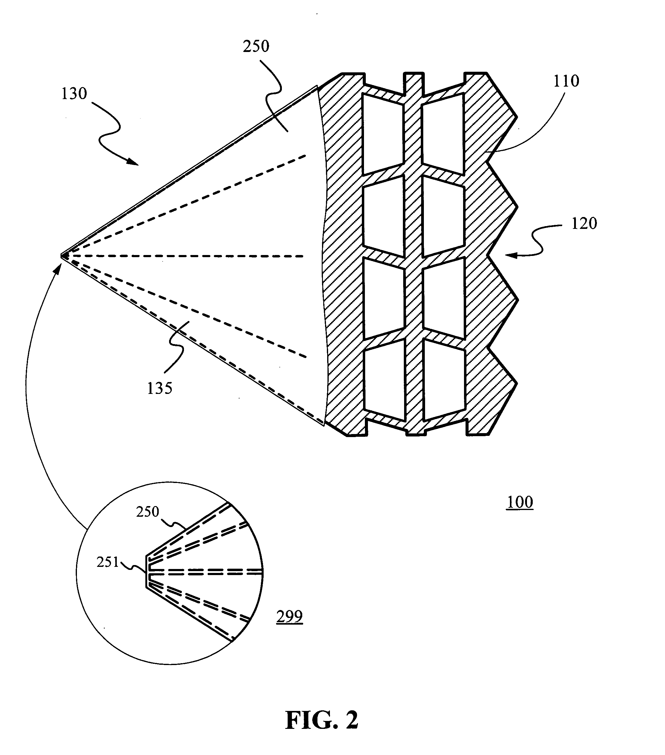
[0012] A biocompatible coating, covering, or a soft structure is then coated, laminated, bonded, or otherwise applied to the final frame structure. Suitable materials include silicones, polyvinyl, polyether-based polyamides, thermoplastic elastomers, polyurethane, polyethylene, anti-blood clotting coatings, anti-thrombogenic coatings, bioactive coatings, and heparin coatings. To enhance and / or strengthen the bonding, surface treatment and / or modification such as etching, polishing, sand blasting, plating, nanotechnology smart molecule bonding, and other techniques, could also be applied.
[0018] In some embodiments, the frame structure is cut, stamped, etched, machined, or otherwise created from a substantially flat (i.e., two-dimensional, e.g., a sheet) or a tubular (i.e., three-dimensional, e.g., a hollow cylinder) material. Alternatively, the frame structure is monolithically formed utilizing injection molding, insert molding, or other precision molding processes. One skilled in the art will appreciate that, compared to the manufacturing processes common in fabricating prior artificial valves, the manufacturing processes necessary to produce the implantable vales according to the present invention are easier, more efficient, and very cost effective.
[0020] Moreover, in some embodiments, the implantable valve can be rolled, folded, or otherwise reduced to an even more compact size. This advantageously enables the implantable valve to be introduced / delivered percutaneously with minimal invasiveness, for instance, via a catheter, which is highly desirable in the field.
[0021] The customizable open end of the implantable valve can also be tailored or otherwise configured in various ways to suit or adapt to different needs and applications. For example, it may have built-in anchoring and / or attachment sites, advantageously eliminating or significantly reducing the need for complex suturing.

Problems solved by technology

However, for various reasons, they often fail to function properly or stop working altogether.
As one skilled in the art knows, abnormal, diseased, non-functioning natural valves can lead to many serious complications, ranging from urinary incontinence to blood pumping insufficiency.
Unfortunately, these prior artificial valves themselves may fail or malfunction for various reasons.
As such, they are quite susceptible to improper integration, which may result in poor support of the valve opening, shorter fatigue life, and other drawbacks known in the art.
Plastics tend to lose integrity, particularly mechanical integrity over time, after many cycles at body temperature, and therefore are not very desirable especially in fatigue or high stress applications.
As one skilled in the art knows, most prior artificial valves are neither suitable for nor can be retrofitted with desirable advanced technologies such as dipping, insert molding, nanotechnology surface modifications.
Most prior artificial valves also lack adequate metallic areas and / or anchoring means for proper attachment.
As a result, they require undesirable complex suturing and relying heavily on the suturing techniques or careful placement of individual surgeons.
What is more, compared to natural valves, prior artificial valves are quite bulky, thus preventing them from being introduced easily in a percutaneous fashion.

Method used


Image

  • Implantable valves and methods of making the same
  • Implantable valves and methods of making the same
  • Implantable valves and methods of making the same

Examples


first embodiment

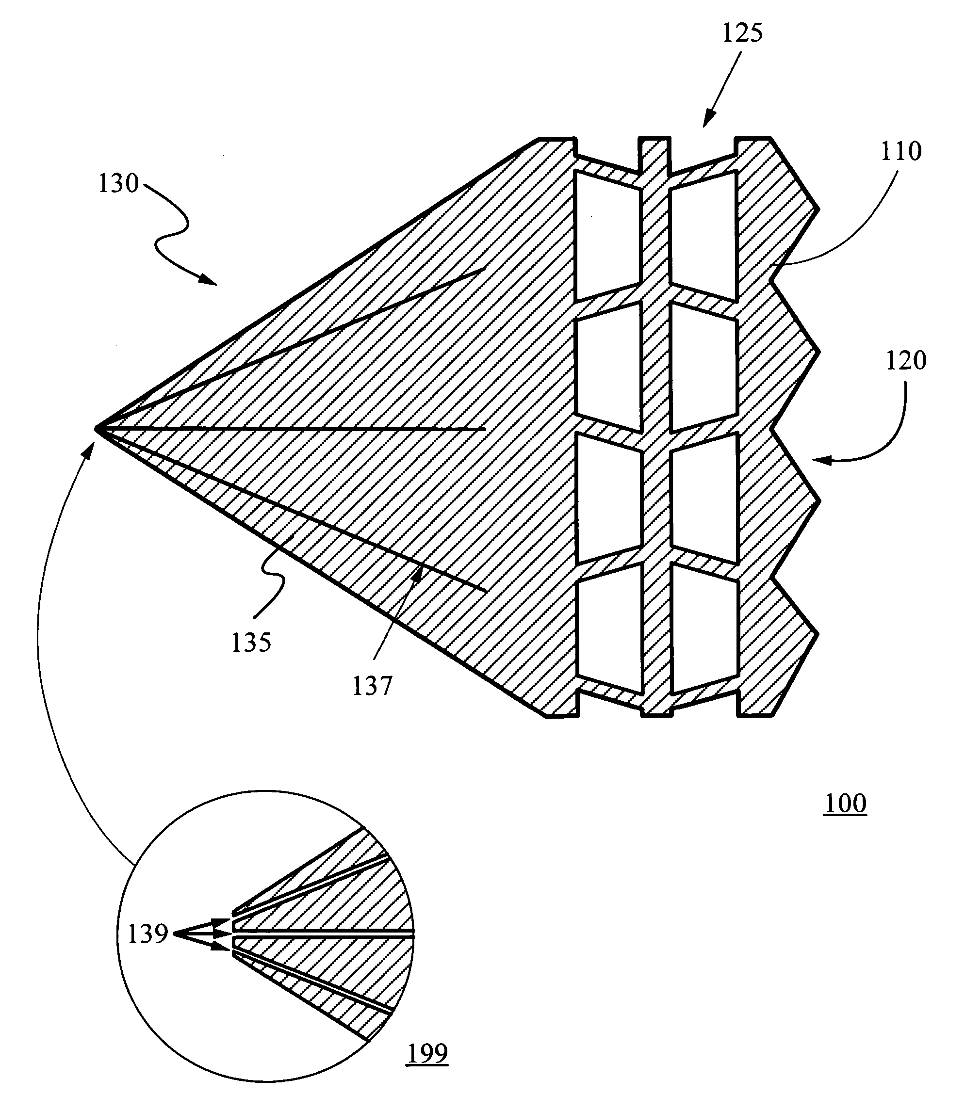
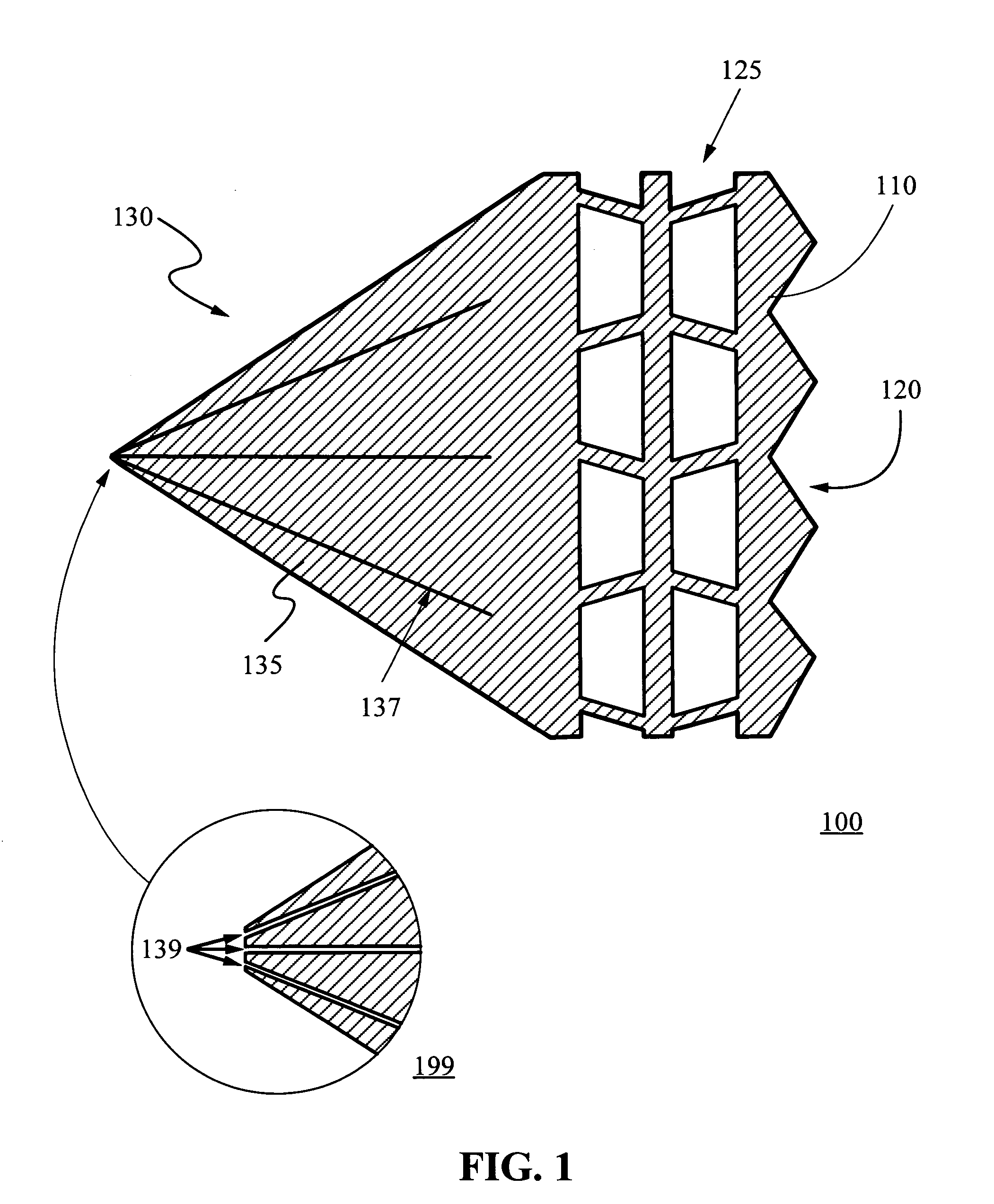
[0037]FIGS. 1-2 show an implantable valve 100 composed of a frame structure 110 monolithically formed from a single piece of material and a biocompatible coating 250. According to the present invention, the single piece of material could be metal or a synthetic material made from the polymerization of organic compounds. The frame structure material preferably has memory, for instance, elastic or heat-recoverable shape memory. Shape memory effect describes the process of restoring the original shape of a plastically deformed material by heating it. This is a result of a crystalline phase change known as “thermoelastic martensitic transformation”.

[0038] Materials suitable for implementing the frame structure of the present invention include, but not limited to, nickel-based alloys such as NITINOL (an acronym for Nickel Titanium Naval Ordnance Laboratory), cobalt-chromium-nickel alloys such as Elgiloy®, metallic and plastic shape memory materials, stainless steel, polyether-block co-po...

third embodiment

[0058]FIG. 5 shows the implantable valve and steps of forming the same according to the present invention. As shown in step 501, the implantable valve 500 is formed from a flat frame structure 510, which is stamped with a pattern (omitted here for clarity) and slits forming an opening 539. The dash line 523 illustratively separates the edges, which forms the open end 520 in step 503, from the opening 539, which forms the tapered end.

[0059] The flat frame structure 510 is rolled up or otherwise turned into a conical shape in step 502 by, for example, sliding it over a mandrel (not shown) and heat set in step 503 at a temperature above 300° C. and mostly at 500° C. for a period of one minute to 30 minutes for shape memory alloys.

[0060] One skilled in the art will readily appreciate that different material requires different temperature and time to set and / or cure. For example, Nitinol is a family of inter-metallic materials that contain a nearly equal mixture of nickel (55 wt. % Ni) ...

fourth embodiment

[0062]FIG. 6 shows the implantable valve and steps of forming the same according to the present invention. In step 601, the implantable valve 600 is formed from a substantially flat frame structure 610, which is cut, stamped, laser cut, etched, or molded from a variety of materials, some of which have shape memory and some do not. The frame structure 610 has an intricate pattern 625 with multiple openings including a central opening 639 and a plurality of attachment sites 635.

[0063] As described above, the frame structure material itself could be substantially flat or tubular. In the latter case, it is possible to carve, etch through, or create cavities inside and around the tubular material and then slice the frame structure 610 alone with the pattern 625. Alternatively, it is possible to slice pieces from the tubular material and then stamp, cut, etch, or laser machine the pattern 625 thereof respectively.

[0064] In step 602, the flat frame structure 610 is rolled up or otherwise ...


PUM


Abstract

An implantable valve composed of a frame structure monolithically formed and covered with a biocompatible coating or soft structure. The implantable valve can have various shapes, openings, anchoring sites, attachment sites and is flexible, expendable, and easy to attach to body tissue. In some embodiments, the implantable valve is made by first determining a two or three dimensional configuration of the frame structure, which has an open end and a tapered end. The configuration may be scaled to obtain a desired size, e.g., length and diameter. One or more frame structure may be cut, stamped, etched, or machined from a single material, which could be metal or plastic with various thickness profiles and may have superelasticity and / or shape memory. The biocompatible coating selectively seals the valve to control / prevent fluid passage. To enhance bonding, the frame structure surface is treated with etching, polishing, sand blasting, plating, nanotechnology surface modification, etc.

Description

BACKGROUND OF THE INVENTION [0001] 1. Field of the Invention [0002] This invention relates generally to valves implantable in a hollow organ or vessel such as the heart or a vein or other body cavities. More particularly, it relates to new and improved implantable valves and methods of making the same, each embodiment thereof is composed of a frame structure formed from a single piece of material and a biocompatible protective coating or soft structure. [0003] 2. Description of the Related Art [0004] Natural valves in the human body as well as other animals have important functions such as controlling blood flow in the venous system, preventing back flow, controlling blood flow from the atrium to the ventricle and into the arterial system, preventing uncontrolled flow from the bladder, and air flow through the pulmonary system or in the gastro-intestinal system. [0005] Intricately situated, these natural valves are supposed to respond to pressure, or the lack thereof, and control / pr...

Claims


Application Information

Patent Timeline
Patent Type & Authority Applications(United States)
IPC IPC(8): A61F2/04A61F2/06A61F2/24
CPCA61F2/2418A61F2230/0067A61F2230/005A61F2/2475
Inventor ZADNO, REZA
Owner ZADNO REZA
Learn More