
System and method for efficient compression of digital data

Active Publication Date: 2007-12-13
NVIDIA CORP
View PDF50 Cites 74 Cited by
  • Summary
  • Abstract
  • Description
  • Claims
  • Application Information

AI Technical Summary

Benefits of technology

[0040]An advantage of the present invention is that it permits more efficient compression of digital data, permitting the digital data to be represented more compactly as well as often permitting either or both of compression and decompression operations to be performed faster and with less processing resources.
[0041]These and other objects and advantages of the present invention will become clear to those skilled in the art in view of the description of the best presently known mode of carrying out the invention and the industrial applicability of the preferred embodiment as described herein and as illustrated in the figures of the drawings.

Problems solved by technology

Since it would be odious and redundant to present examples of both loss-less and lossy type compression across the entire range of potential applications, the examples presented herein relate primarily to lossy type compression applied to video type data.
Unfortunately, the data characteristics discussed above only hold true when the block-motion model offers a good description of the underlying video process, resulting in a residue with small energy and a low-frequency characteristic.
However, there are many occasions where a natural video phenomenon will contain motion that is far more complex than can be captured by the block-motion model.
As a result, the syntax elements for the data bit stream that are tuned for the more commonly occurring low-frequency residue case instead offer a poor description of the residue information, resulting in higher bit-rates and poor compression.
Generalizing now beyond H.264 and video to compression of all types of bandwidth limited data, when high-frequency data is encountered it is less efficiently handled and represented than low-frequency data.
Among those few skilled in the art who have appreciated this previously, this has generally been reconciled as being too inconsequential to merit remedial efforts or as requiring such efforts that would be too burdensome to result in a net improvement.
However, as discussed extensively below, it has been the present inventors' observation that such inefficiency is frequently consequential and it has been their labor to devise an elegant remedy for that.

Method used


Image

  • System and method for efficient compression of digital data
  • System and method for efficient compression of digital data
  • System and method for efficient compression of digital data

Examples


Embodiment Construction

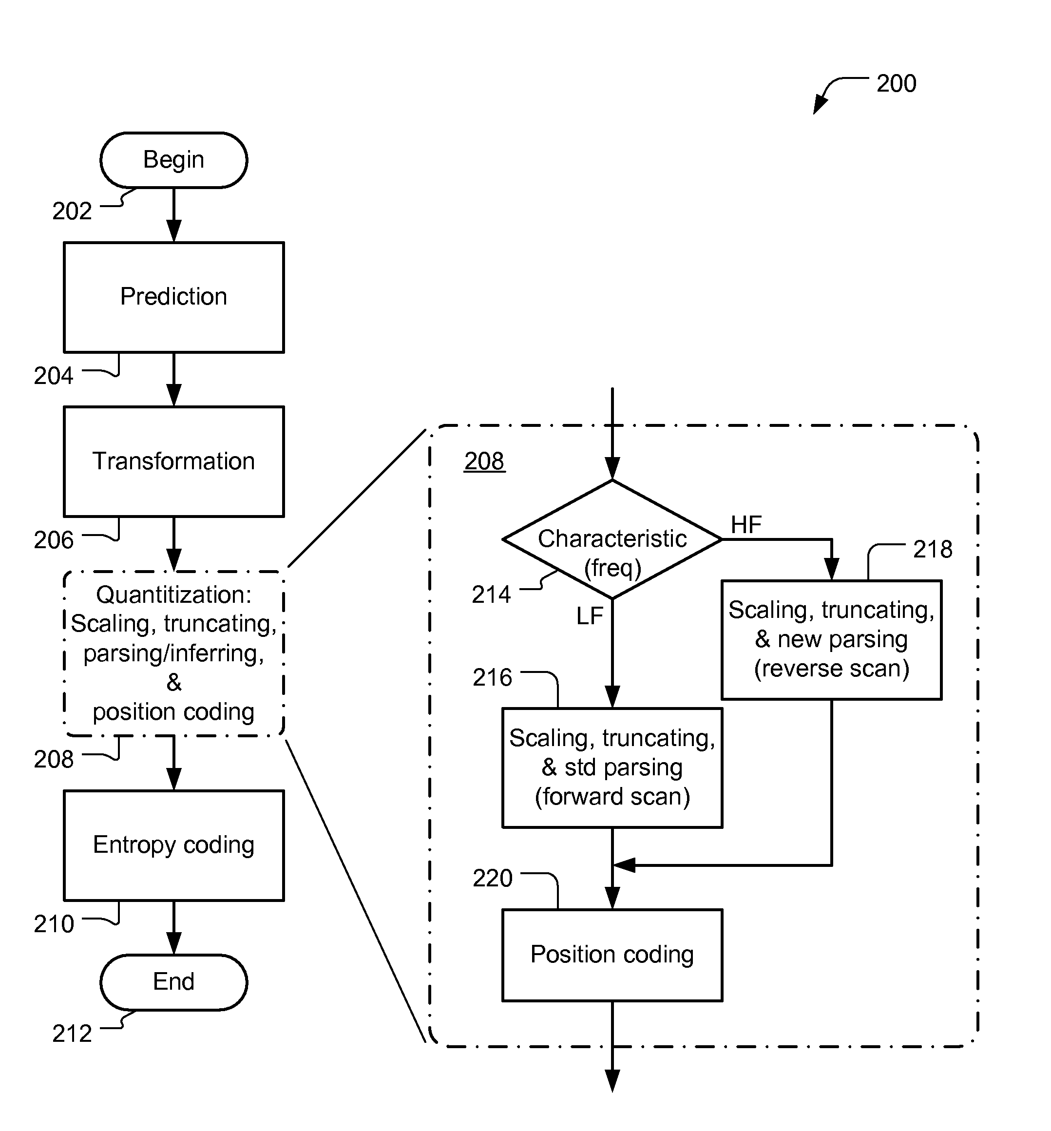
[0053]A preferred embodiment of the present invention is apparatus and method for efficient compression of digital data. As illustrated in the various drawings herein, and particularly in the views of FIG. 5 and FIG. 8, preferred embodiments of the invention are depicted by the general reference characters 100 and 200.

[0054]In the context of H.264 video compression the present inventors have observed that poor compression efficiency results for high frequency residue information because the Huffman tables for syntax elements, such as “total_zeros,” are tuned for video content where these syntax elements take smaller values. As described above, in the Background Art section, these syntax elements tend to take larger values in the high frequency case, hence requiring more bits to represent them and resulting in poor compression.

[0055]Briefly, the present inventors have devised a way to counter this by adding flexibility to the interpretation of the syntax elements “total_zeros” and “r...


PUM


Abstract

A system for compressing digital data by representing a portion of it predictionally and transformationally as a block of transform coefficients, then quantizing that block selectively into a set of encoding symbols based on an indication whether the transform coefficients represent the portion as having a particular characteristic, and then by encoding the set of encoding symbols into a data bit stream. In particular, frequency may be used as the characteristic of the digital data in many applications.

Description

TECHNICAL FIELD[0001]The present invention relates generally to coded data generation or conversion, and more particularly to converting digital signals representing information into a different system of digital signals representing substantially the same information more compactly.BACKGROUND ART[0002]The following pertains generally to digital data compression as it may be employed in many applications. Since it would be odious and redundant to present examples of both loss-less and lossy type compression across the entire range of potential applications, the examples presented herein relate primarily to lossy type compression applied to video type data. Video type data is especially challenging and of particular concern to industry presently, and lossy type compression techniques are well suited for compressing it and typically permit more notable efficiency increases. The choice of these as examples, however, should not be construed as implying limitations in the technical princ...

Claims


Application Information

Patent Timeline
IPC IPC(8): H03M7/00
CPCH04N19/105H04N19/70H04N19/46H04N19/91H04N19/60H04N19/103H04N19/124H04N19/129
Inventor PURI, ROHITSRIRAM, PARTHASARATHY
Owner NVIDIA CORP
Learn More