Smoke and clean air generating machine for detecting the presence and location of leaks in a fluid system

Inactive Publication Date: 2006-03-16
CPS PRODS
View PDF6 Cites 3 Cited by
  • Summary
  • Abstract
  • Description
  • Claims
  • Application Information

AI Technical Summary

Benefits of technology

[0010] As an alternate embodiment of the present invention, the air compressor to deliver clean air to the flow meter and the smoke generating apparatus can be replaced by a pressure and flow regulated source of non-flammable nitrogen gas. In this case, a mixture of nitrogen (rather than air) and smoke will travel through the smoke outlet line to be delivered to the system under test so that a relatively safe, non-explosive environment can be established, particularly in situations characterized by high temperatures.

Problems solved by technology

The problem is that this conventional method of testing for leaks in the vapor recovery system of a motor vehicle does not take into account the volume of fuel stored in the gas tank.
More particularly, for a vehicle with less fuel and a larger air space in its tank, it will take a longer time to detect a leak.
Therefore, the test operator can receive a false indication as to the integrity of the evaporative system, because of the increased time that is required for this system having an air accumulator to be fully pressurized.
Consequently, an evaporative system which shows that it is holding pressure over time may actually have a leak and be in need of repair to avoid emissions to the atmosphere.

Method used


Image

  • Smoke and clean air generating machine for detecting the presence and location of leaks in a fluid system
  • Smoke and clean air generating machine for detecting the presence and location of leaks in a fluid system
  • Smoke and clean air generating machine for detecting the presence and location of leaks in a fluid system

Examples


Embodiment Construction

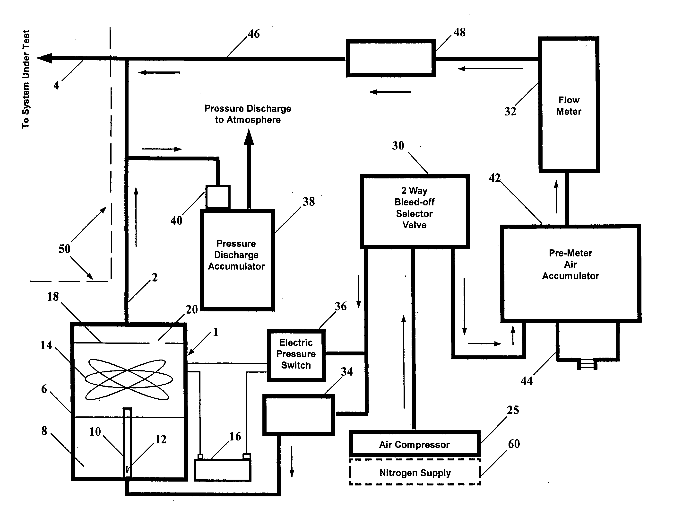
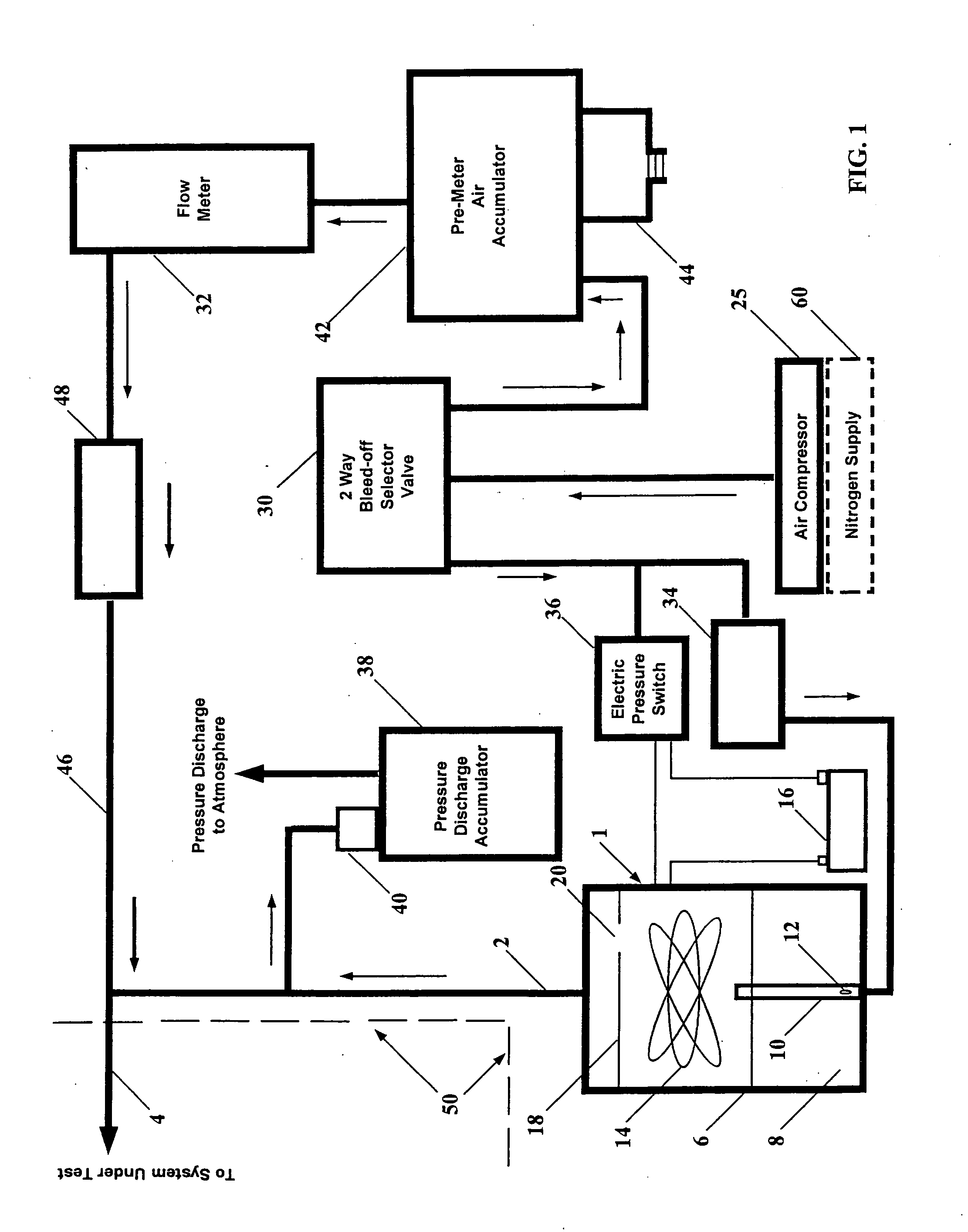
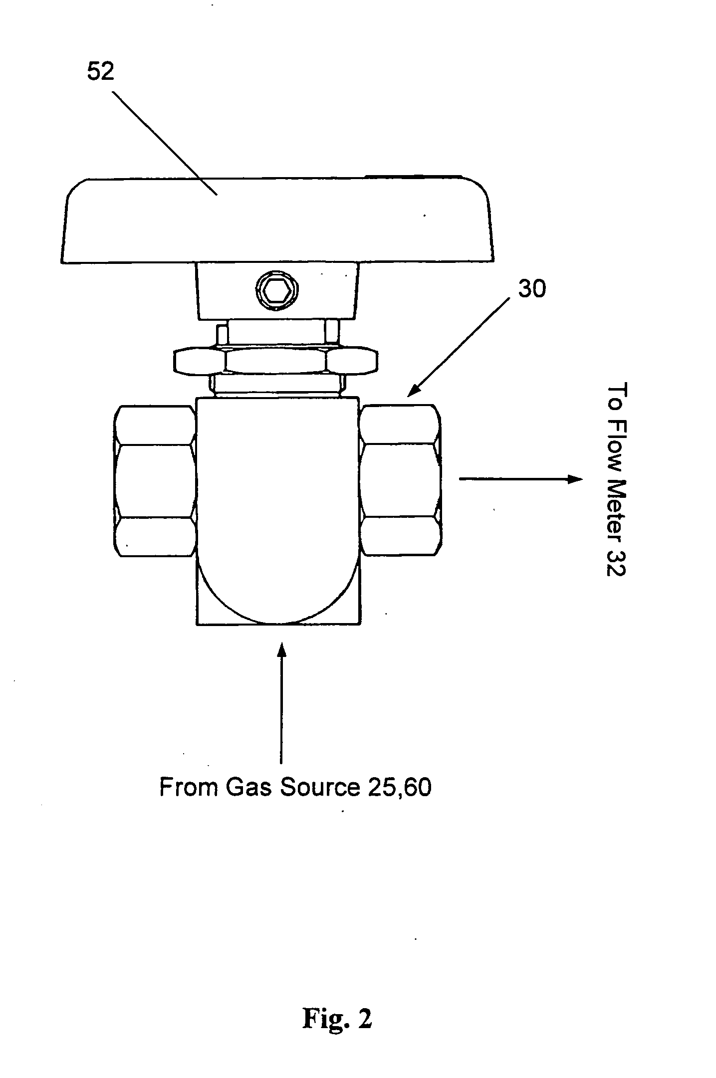
[0015] Referring to the drawings, there is shown in FIG. 1 a smoke and clean air generating machine having an outer casing (designated by phantom lines) 50 within which is housed a smoke generating apparatus 1 that is adapted to generate a supply of smoke to a smoke outlet line 2 and a smoke supply line 4 so that a fluid system (not shown) can be visually inspected for leaks. The smoke generating apparatus 1 has been described in detail in our earlier patent application Ser. No. 09 / 020,841 filed Feb. 9, 1998, the teachings of which are incorporated herein by reference. Therefore, a full description of the smoke generating apparatus 1 will not be provided.

[0016] Briefly, however, the smoke generating apparatus 1 includes a sealed chamber 6 which contains a non-toxic oil supply 8. An air inlet tube 10 projects upwardly from the bottom of chamber 6 and extends above the oil supply 8. Inlet tube 10 communicates with an external air compressor 25 through a wall of chamber 6. An inlet or...


PUM


Abstract

A smoke and clean air generating machine for detecting the presence and location of leaks in a fluid system (e.g. the evaporative or brake system of a motor vehicle). A source of gas (e.g. air or nitrogen) under pressure is delivered to a smoke generating apparatus or to a flow meter by way of a multi-position selector valve. With the selector valve in a first position, gas is delivered to the system under test via the flowmeter to detect the presence of a leak in need of repair depending upon the reading of the flow meter. With the selector valve in a second position, gas is delivered to the smoke generating apparatus so that smoke can be supplied to the system under test to locate the leak. With the selector valve in a third position between the first and second positions, pressure is bled from the machine to disable the smoke generating apparatus and thereby terminate the production of smoke.

Description

BACKGROUND OF THE INVENTION [0001] 1. Field of the Invention [0002] This invention relates to a compact, easy to use and portable smoke and clean air generating machine that enables the presence and location of leaks in a fluid system (e.g. the evaporative or brake system of a motor vehicle) to be accurately and visually detected depending upon the rate of air flow through the fluid system under test and whether smoke escapes from the system. [0003] 2. Background Art [0004] Our patent application Ser. No. 09 / 020,841 filed Feb. 9, 1998 and entitled SMOKE PRODUCING APPARATUS FOR DETECTING LEAKS IN A FLUID SYSTEM discloses an efficient, portable apparatus for generating smoke in order to locate leaks in a fluid (e.g. air, oil, fuel, exhaust, etc.) system. A supply of oil within a sealed chamber is vaporized, and the resulting smoke is delivered to the system under test. By visually inspecting the system for smoke escaping therefrom, the precise location of a leak in the system can be a...

Claims


Application Information

Patent Timeline
IPC IPC(8): G01M3/04G01M3/20G01M3/28
CPCG01M3/2807G01M3/20
Inventor PIERONI, KENNETH ALANSAFFIE, JIM ELI
Owner CPS PRODS
Why Eureka
Try Eureka