Electronic candle assembly and methods of use

Active Publication Date: 2016-02-23
LLORET ANTONIO R
View PDF8 Cites 8 Cited by
  • Summary
  • Abstract
  • Description
  • Claims
  • Application Information

AI Technical Summary

Benefits of technology

This patent describes an electronic candle assembly that looks and works like a real candle. It can be used in environments where real candles are not safe or allowed. Additionally, it provides a safer alternative for common situations where candles are used. The electronic design has a flame that can be turned off from multiple directions. Overall, this invention offers an aesthetically pleasing and safe alternative for simulating the flame of a candle.

Problems solved by technology

However, due to the circuitry used, the shape of the candles of Chan does not resemble the thin stem of a candle such as a birthday candle.
However, Wong requires a user to blow at a certain part of the candle, not generally around or on the light.

Method used


Image

  • Electronic candle assembly and methods of use
  • Electronic candle assembly and methods of use
  • Electronic candle assembly and methods of use

Examples


Embodiment Construction

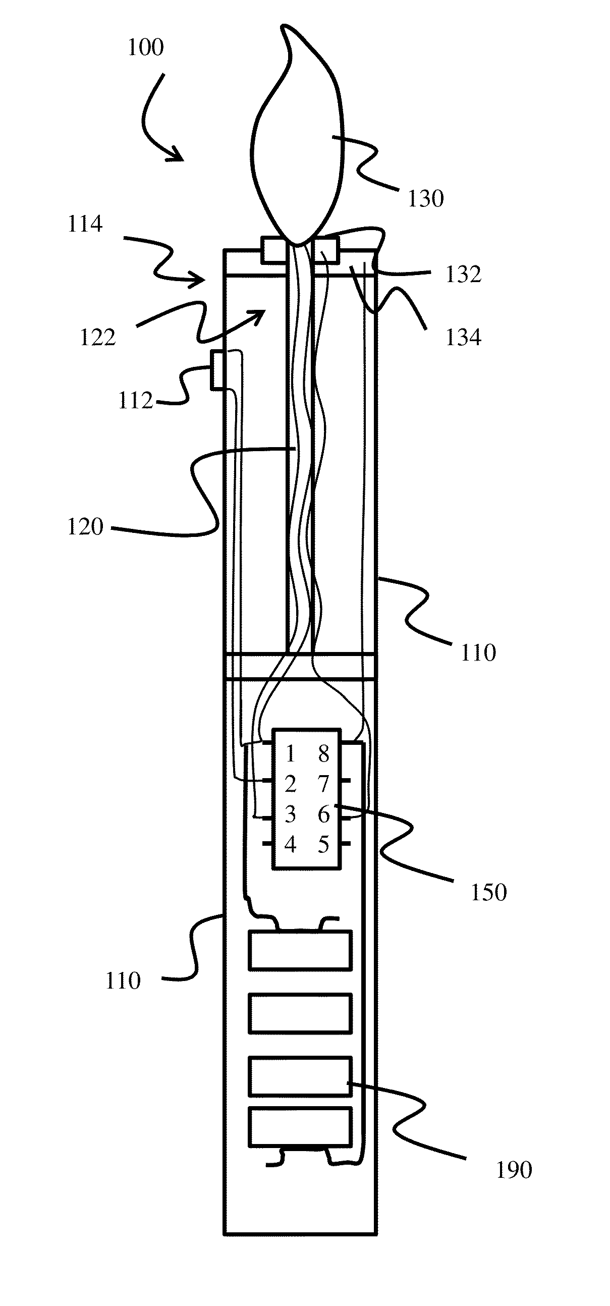
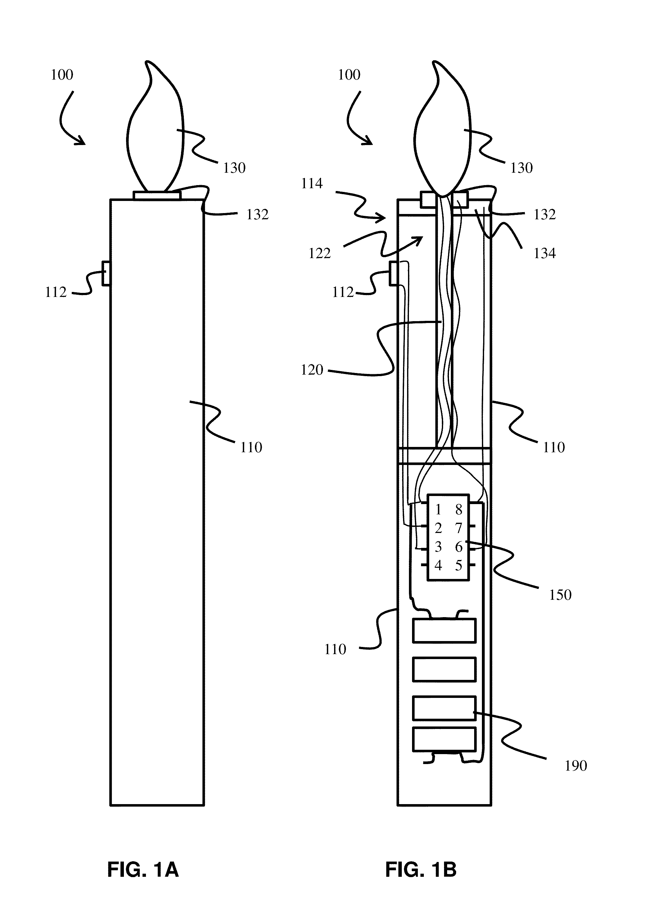
[0039]Switchable electric devices and methods of use will now be described in detail with reference to the accompanying drawings. It will be appreciated that, while the following description focuses on a switchable systems such as electronic candle assemblies that provide a light switched by a blowing force, the systems and methods disclosed herein have wide applicability. For example, the electronic candle assembly is one embodiment of a switchable electric device as disclosed and such switchable devices may be readily employed with wind sensitive switches, tilt switches or other electronic assemblies that benefit from a sensitive switching mechanism. Notwithstanding the specific example embodiments set forth below, all such variations and modifications that would be envisioned by one of ordinary skill in the art are intended to fall within the scope of this disclosure.

One Embodiment of the Electronic Candle Assembly:

[0040]The electric candle assembly generally comprises a body, a ...


PUM


Abstract

An electric candle assembly is disclosed comprising a body, a light, a power source conductively attached to a control element, control circuitry to control the conductivity between the power source and the light, the control circuitry comprises a threshold circuit to switch the light from an on mode to an off mode and the threshold circuit is configured to receive a force on the light from a gas whereby the force moves the light and moves the second threshold switch contact from an unflexed position to a flexed position and switches the light from the on mode to the off mode. In some embodiments the control element is an integrated circuit such as a 555 integrated circuit. Embodiments of methods to use the candle assembly are also disclosed.

Description

CROSS-REFERENCE TO RELATED APPLICATIONS[0001]This application claims the benefit of U.S. App. No. 61 / 835,956, filed on Jun. 17, 2013, entitled “L.E.D. Birthday / Occasion Candle,” the entire contents of which are incorporated herein by reference.STATEMENT REGARDING PRIOR DISCLOSURES BY THE INVENTOR OR A JOINT INVENTOR[0002]Not ApplicableSTATEMENT REGARDING FEDERALLY SPONSORED RESEARCH OR DEVELOPMENT[0003]Not ApplicableTHE NAMES OF THE PARTIES TO A JOINT RESEARCH AGREEMENT[0004]Not ApplicableREFERENCE TO SEQUENCE LISTING, A TABLE, OR A COMPUTER PROGRAM LISTING COMPACT DISC APPENDIX[0005]Not ApplicableBACKGROUND OF THE INVENTION[0006]1. Field of the Invention[0007]This application relates to electronically powered devices, in particular electronically powered lights that are capable of being switched on an off by a small force such as blowing on an area of the device.[0008]2. Description of the Prior Art[0009]Electrically powered lights, in particular battery powered candles are now ava...

Claims


Application Information

Patent Timeline
IPC IPC(8): F21L19/00F21S10/04H05B33/08H05B37/02H05B44/00
CPCF21S10/04H05B33/08H05B37/02F21S9/02F21V23/04F21V23/0442F21W2121/00H05B45/32
Inventor LLORET, ANTONIO, R.
Owner LLORET ANTONIO R
Why Eureka
Try Eureka