
Optical disk

a technology of optical disks and optical disks, applied in the field of optical disks, can solve the problems of deterioration of recording characteristics, high modulation factor of dvd-r, thermal interference between recording marks, etc., and achieve the effects of low solubility, high solubility, and low solubility of cyanine dyes in solvents

Inactive Publication Date: 2006-03-02
TDK CORPARATION
View PDF4 Cites 3 Cited by
  • Summary
  • Abstract
  • Description
  • Claims
  • Application Information

AI Technical Summary

Benefits of technology

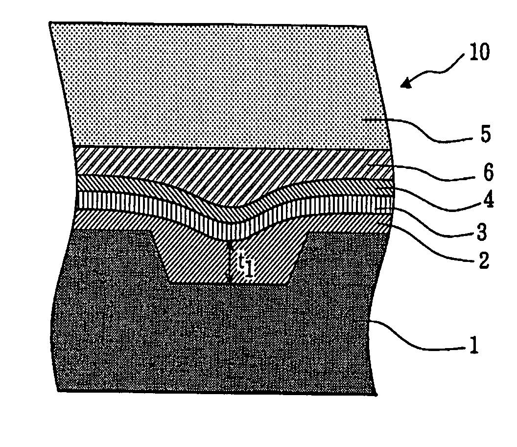
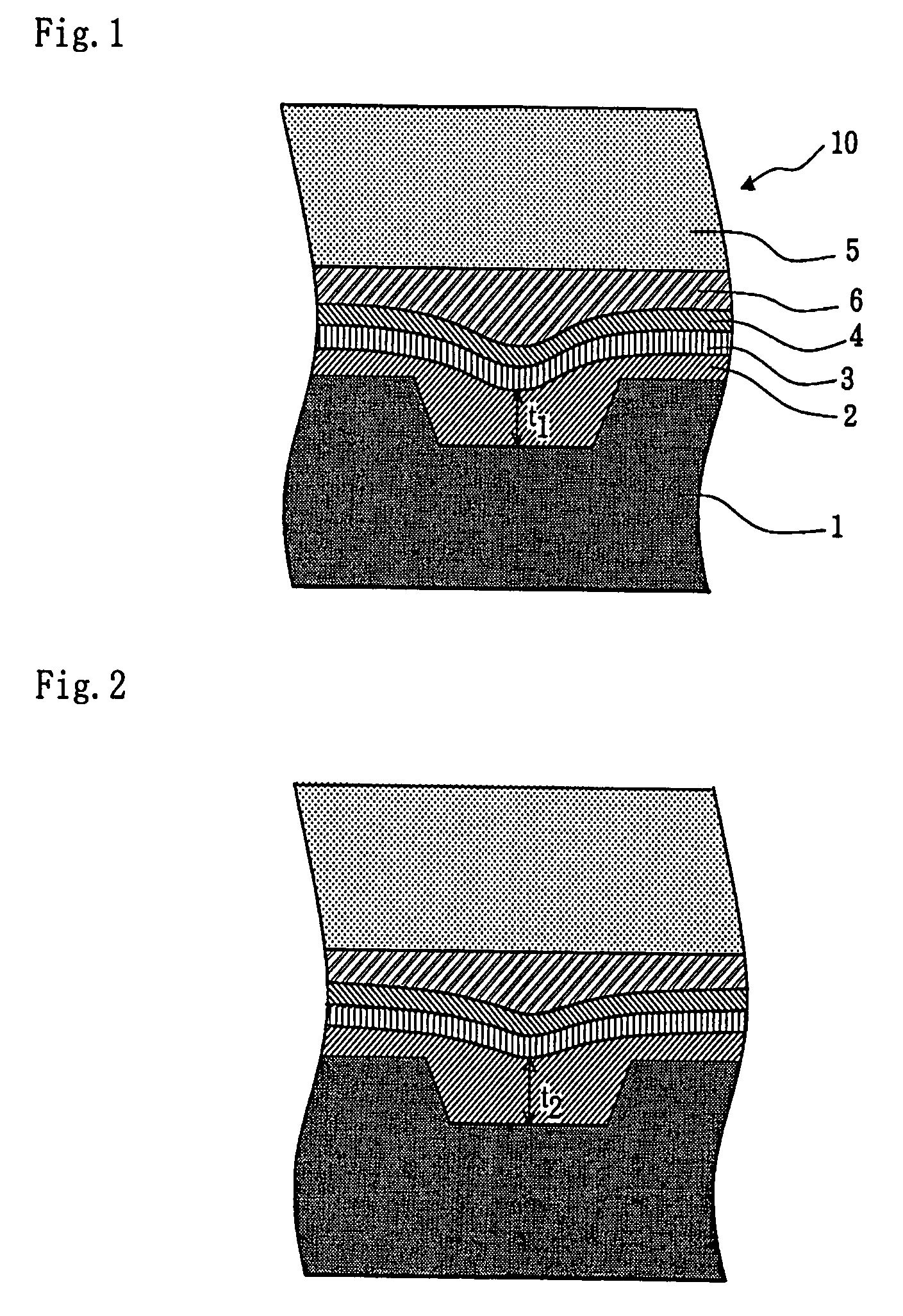
The present invention provides an optical disk with excellent recording characteristics at any recording speed ranging from low speed to high speed. This is achieved by modifying a cyanine dye used as a material of a recording layer such that the dye does not excessively remain in a groove in a substrate. The invention also involves using a fluoroalcohol solvent to apply the cyanine dye to the substrate, which results in the appropriate control of the thickness of the cyanine dye in the groove and on a land. Overall, the invention prevents excessive amounts of cyanine dye from remaining in the groove, minimizes thermal interference, and achieves both excellent jitter characteristics and a smaller increase in the modulation factor.

Problems solved by technology

However, use of the conventional dye and the solvent leaves excessive dye in the groove, causing thermal interference between recording marks.
The thermal interference causes deterioration in recording characteristics.
Thus, the DVD-R has the problem of the higher modulation factor due to the higher laser output in the high-speed recording.
In a certain case, the recording mark overhangs a pre-pit in a land, making address control difficult.

Method used


Image

  • Optical disk
  • Optical disk
  • Optical disk

Examples


example 1

[0038] A cyanine dye having the following chemical formula II was prepared, wherein the counter ion (X−) was PF6−.

[0039] (II)

[0040] This cyanine dye was dissolved in 2,2,3,3-tetrafluoro-1-propanol at a concentration of 14 mg / ml. The cyanine dye solution was applied to an optically transparent substrate 1 by spin coating to form a recording layer 2.

[0041] Then, a reflective layer 3 was formed on the recording layer 2. A top coat was applied to the reflective layer 3 to form a protective layer 4. A dummy substrate 5 was laminated on the protective layer 4. In this way, an optical disk 1 was manufactured.

example 2

[0042] An optical disk 1 was manufactured by the same procedures as in the Example 1, except that the cyanine dye having the chemical formula II in the Example 1 was replaced by a cyanine dye having the following chemical formula III.

[0043] (III)

example 3

[0044] An optical disk 1 was manufactured by the same procedures as in the Example 1, except that the cyanine dye having the chemical formula II in the Example 1 was replaced by 50% by mole of cyanine dye having the chemical formula III and 50% by mole of cyanine dye having the chemical formula IV.

[0045] (IV)


PUM

PropertyMeasurementUnit
solubilityaaaaaaaaaa
thicknessaaaaaaaaaa
speedaaaaaaaaaa

Abstract

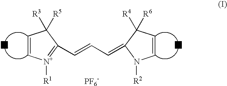
An optical disk having excellent recording characteristics at both low speed and high speed is provided by modifying a cyanine dye serving as a material of a recording layer such that the cyanine dye does not excessively remain in a groove in an optically transparent substrate. The optical disc comprises the recording layer on a surface of the optically transparent substrate, a reflective layer on the recording layer, and a protective layer on the reflective layer, wherein the recording layer contains at least one cyanine dye expressed by the following chemical formula I: wherein, R1, R2 R3, R4, R5, and R6 are hydrocarbon groups, and A and B are independently a fused benzene ring or a fused naphthalene ring optionally having a substituent, and wherein the recording layer is formed by applying the at least one cyanine dye in a fluoroalcohol solvent to the optically transparent substrate.

Description

BACKGROUND OF THE INVENTION [0001] 1. Field of the Invention [0002] The present invention relates to an optical disk, and particularly to a write-once read-many optical disk having excellent read-write characteristics at any recording speed ranging from low speed to high speed. [0003] 2. Description of the Related Art [0004] As the progress of technology, various optical recording media, including a compact disc (CD) and a digital versatile disc (DVD), have been proposed and developed. Among these, recordable optical recording media include write-once read-many optical disks, such as a CD-R and a DVD-R. [0005] In general, the write-once read-many optical disk contains an organic dye, such as an azo dye or a cyanine dye, as a recording material. The organic dye in a solvent is coated on a substrate to form a recording layer. Thus, it is important for the organic dye to have excellent recording characteristics at the wavelength of a laser beam applied to the organic dye and have adequ...

Claims


Application Information

Patent Timeline
Patent Type & Authority Applications(United States)
IPC IPC(8): B32B3/02G11B7/24035G11B7/2472G11B7/2495
CPCG11B7/2467G11B7/2472G11B7/248G11B7/2495G11B7/252G11B7/2531Y10T428/21G11B7/2535G11B7/2536G11B7/256G11B7/259G11B2007/24612G11B7/2534
Inventor HORAI, TAKASHI
Owner TDK CORPARATION
Learn More