Thin-film magnetic head, method of manufacturing the same, head gimbal assembly, and hard disk drive

a technology of thin-film coils and magnetic heads, which is applied in the manufacture of flux-sensitive heads, instruments, and record information storage, etc., can solve the problems of increasing the heat generated by thin-film coils, affecting the recording quality of the recording medium, and achieving excellent recording characteristics

Active Publication Date: 2005-08-25
HEADWAY TECH INC +1
View PDF8 Cites 0 Cited by
  • Summary
  • Abstract
  • Description
  • Claims
  • Application Information

AI Technical Summary

Benefits of technology

[0022] For solving the problems mentioned above, it is an object of the present invention to provide a thin-film magnetic head comprising a structure yielding excellent recording characteristics in high frequency bands without raising the ohmic value, a method of manufacturing the same, a head gimbal assembly, and a hard disk drive.

Problems solved by technology

Since most of magnetic fluxes are generated about the junction in the former thin-film magnetic heads, however, only about a few percent of the generated magnetic fluxes is used for recording, so that the recording with magnetic fluxes is not carried out efficiently.
However, narrowing the turn width in the thin-film coil raises the ohmic value of the thin-film coil, thereby increasing the heat generated from the thin-film coil.
As a consequence, the magnetic pole parts project toward the recording medium, and are likely to collide with the recording medium.
Therefore, conventional thin-film magnetic heads have been unable to make the turn width so small.
The wall part must have a certain extent of width in order to keep its shape, which makes it difficult to reduce the interval between adjacent turns (turn interval) when forming a thin-film coil by frame plating.

Method used


Image

  • Thin-film magnetic head, method of manufacturing the same, head gimbal assembly, and hard disk drive
  • Thin-film magnetic head, method of manufacturing the same, head gimbal assembly, and hard disk drive
  • Thin-film magnetic head, method of manufacturing the same, head gimbal assembly, and hard disk drive

Examples


first embodiment

[0107] Structure of Thin-Film Magnetic Head

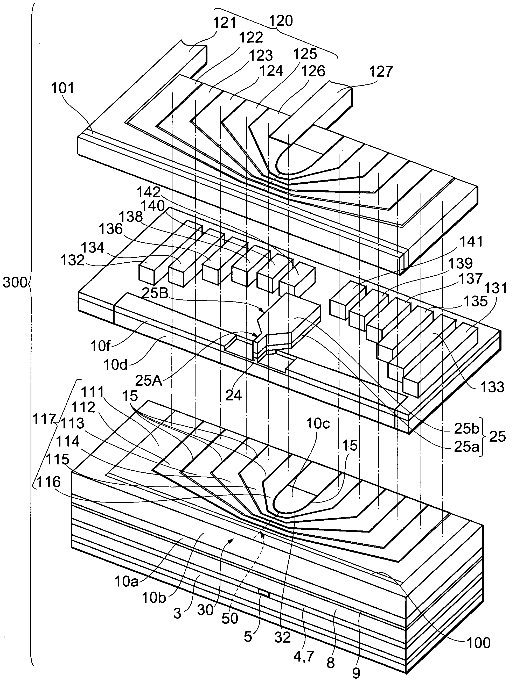
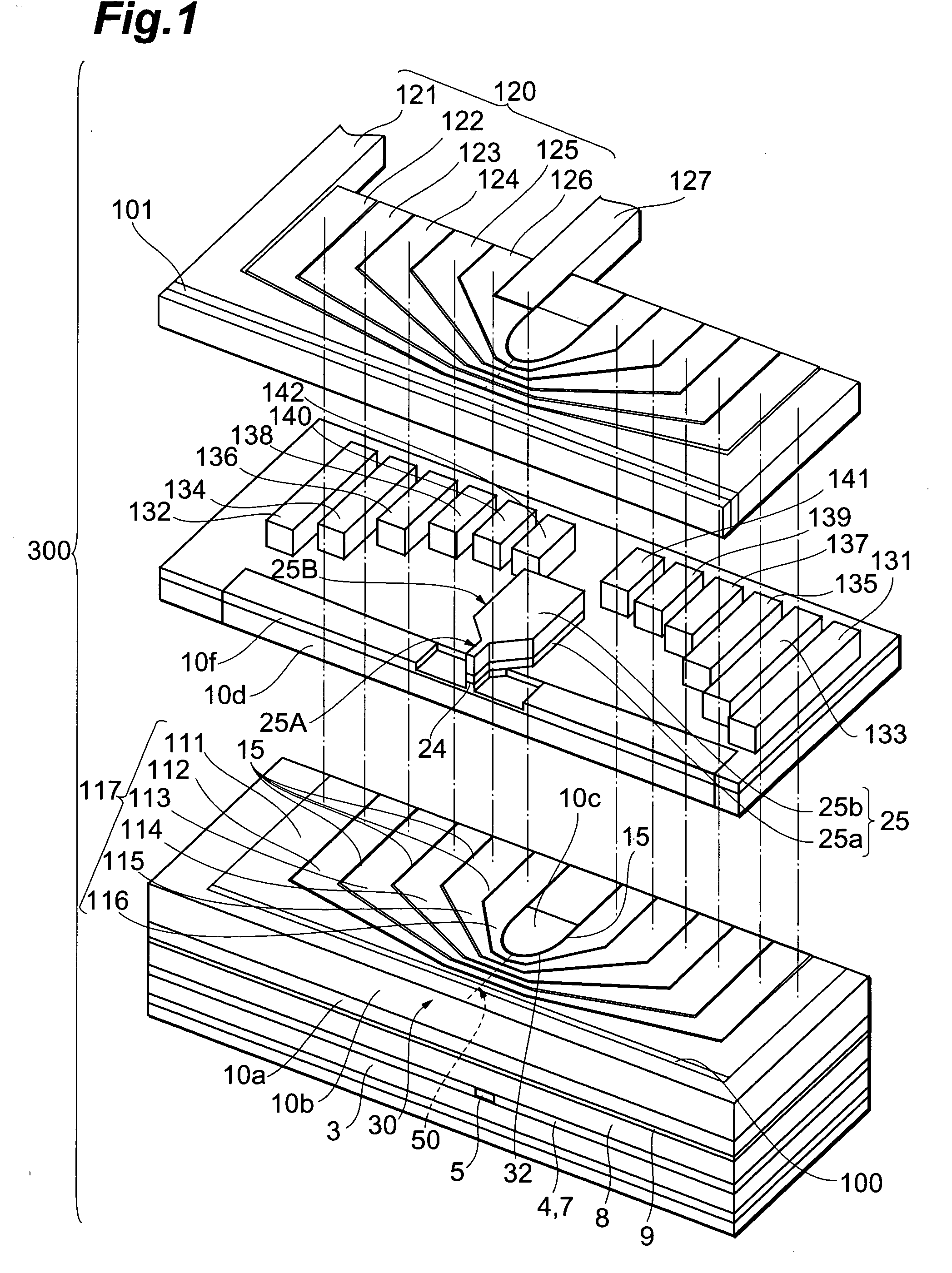
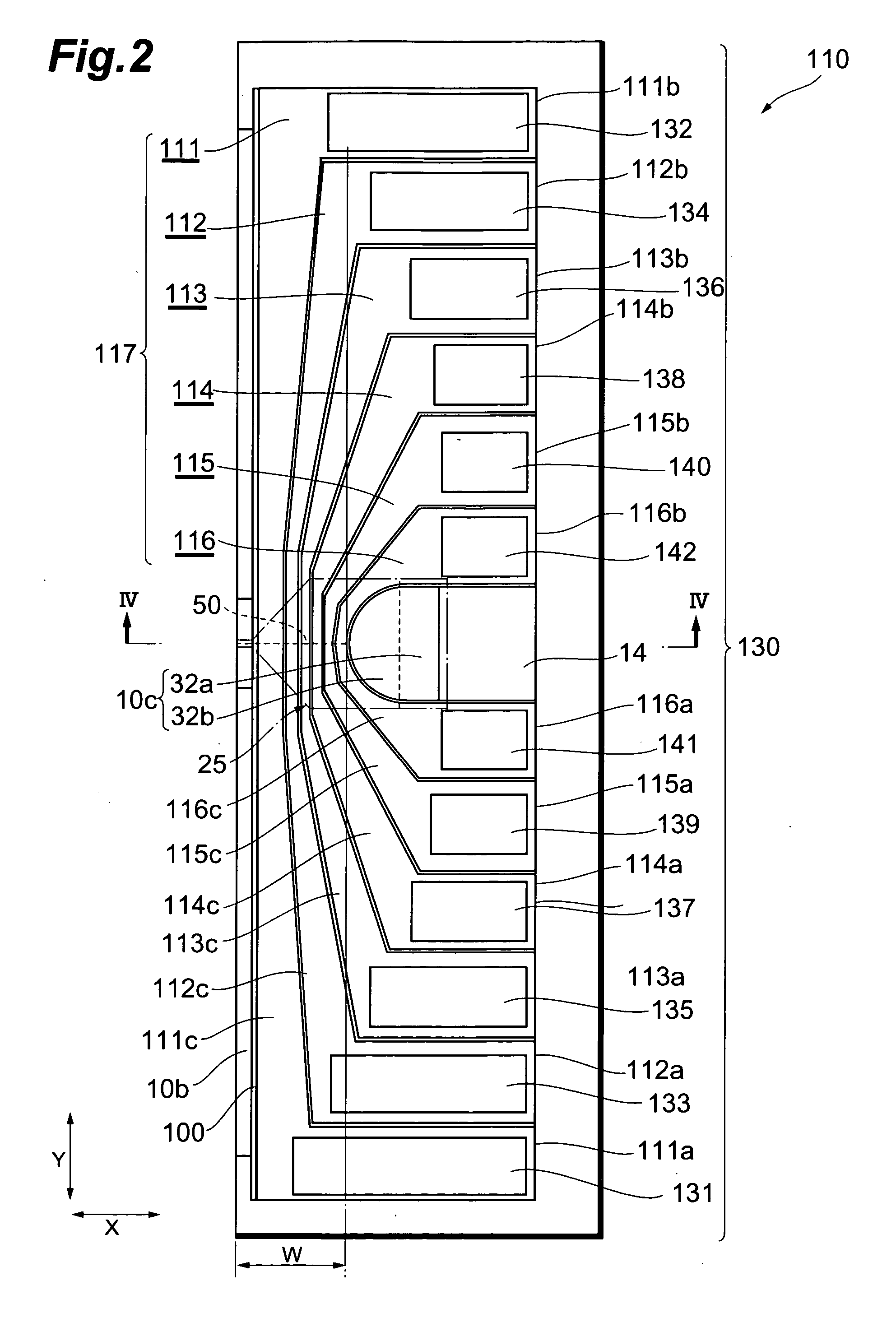
[0108] First, with reference to FIGS. 1 to 4, the structure of the thin-film magnetic head in accordance with the first embodiment of the present invention will be explained. Here, FIG. 1 is an exploded perspective view showing a main part of the thin-film magnetic head 300 in accordance with the first embodiment of the present invention. FIG. 2 is a plan view showing a first conductor group 117 and a connecting part group 130 which constitute a thin-film coil 110, whereas FIG. 3 is a plan view similarly showing a second conductor group 120. FIG. 4A is a sectional view taken along the line IV-IV of FIG. 2, whereas FIG. 4B is a sectional view parallel to an air bearing surface 30.

[0109] The thin-film magnetic head 300 in accordance with the first embodiment comprises a substrate 1, and a reproducing head and a recording head (inductive electromagnetic transducer) which are laminated on the substrate 1, while having the air bearing surface ...

first modified example

[0185] The thin-film magnetic head 300 in accordance with the first modified example is the same as that mentioned above except for the configuration of the thin-film coil, and thus will be explained in terms of their difference while omitting or simplifying their common features. FIG. 26 is a plan view showing the first conductor group 117 and connecting parts in the thin-film coil in the first modified example, whereas FIG. 27 is a plan view similarly showing the second conductor group 120.

[0186] As shown in FIGS. 26 and 27, the thin-film coil in the first modified example comprises the first conductor group 117, second conductor group 120, and connecting part group 130, whereas the configuration of the connecting part group 130 differs from that of the first embodiment. The connecting part group 130 in the first modified example comprises a plurality of connecting parts 131 to 142 which are arranged at respective positions such that the distance from the air bearing surface 30 v...

second modified example

[0191] The thin-film magnetic head 300 in the second modified example is the same as that of the first embodiment except that it comprises a thin-film coil having a configuration different from that of the thin-film coil 110 and that relaxing parts are formed at different positions, and thus will be explained in terms of their differences while omitting or simplifying their common features. FIGS. 28A and 28B are sectional views similar to FIGS. 4A and 4B in the second modified example.

[0192] As shown in FIGS. 28A and 28B, the thin-film coil in this modified example comprises the first conductor group 117, second conductor group 120, and connecting part group 130, but differs from the first thin-film coil 110 in that a series of 5-turn loops are formed in total and that the second conductor group 120 has no insulating contact structure. The first conductor group 117 comprises inner conductors 111, 112, 113, 114, 115 which are in contact with each other by way of a separation insulat...


PUM

PropertyMeasurementUnit
widthaaaaaaaaaa
thicknessaaaaaaaaaa
thicknessaaaaaaaaaa

Abstract

A thin-film magnetic head comprises first and second magnetic pole groups, magnetically connected to each other, having respective magnetic pole parts opposing each other on a side of a medium-opposing surface; a recording gap layer formed between the magnetic pole parts; and a thin-film coil insulated from the first and second magnetic pole groups and wound helically about at least one of them or flatly spirally wound about a junction connecting the first and second magnetic pole groups to each other; which are laminated on a substrate. The thin-film coil comprises a first conductor group having a plurality of inner conductor parts disposed between the first and second magnetic pole groups, and a second conductor group having a plurality of outer conductor parts disposed outside the second magnetic pole group or junction. The first conductor group has an insulating contact structure in which the inner conductor parts are in contact with each other by way of an insulating film. An inner relaxing part comprising a material softer than at least one of the first, second conductor groups and the first, second magnetic pole groups and being in contact with the first conductor group by way of an insulating film is provided.

Description

BACKGROUND OF THE INVENTION [0001] 1. Field of the Invention [0002] The present invention relates to a thin-film magnetic head comprising at least an inductive electromagnetic transducer, a method of manufacturing the same, a head gimbal assembly, and a hard disk drive. [0003] 2. Related Background Art [0004] In recent years, the areal density of hard disk drives has been improving remarkably. Most recently, the areal density of hard disk drives has reached 160 to 200 Gbytes / platter in particular and is about to exceed this level. As a consequence, thin-film magnetic heads are required to improve their performances. [0005] Widely used as a thin-film magnetic head is a combination thin-film magnetic head having a structure in which a recording head comprising an inductive electromagnetic transducer for writing and a reproducing head comprising a magnetoresistive device (hereinafter also referred to as MR device) for reading are laminated. [0006] In this kind of combination thin-film ...

Claims


Application Information

Patent Timeline
Patent Type & Authority Applications(United States)
IPC IPC(8): G11B5/17G11B5/31G11B5/33G11B5/48
CPCG11B5/4826G11B5/33
Inventor SASAKI, YOSHITAKAKAMIGAMA, TAKEHIRO
Owner HEADWAY TECH INC
Why Eureka
Try Eureka