
Scalable tiled display assembly for forming a large-area flat-panel display by using modular display tiles

Inactive Publication Date: 2006-03-02
ADVANTECH GLOBAL LTD
View PDF7 Cites 135 Cited by
  • Summary
  • Abstract
  • Description
  • Claims
  • Application Information

AI Technical Summary

Benefits of technology

[0010] The present invention is a scalable tiled display assembly for forming a large-area flat-panel display by using display tiles that are easily assembled in a modular fashion. The scalable tiled display assembly of the present invention is formed of an array of independently addressed display tiles that are assembled in a modular fashion to achieve a seamless large-area flat-panel display of any desired size. Additionally, column and row drivers are integrated within each display tile for improved performance and minimal external connections. Furthermore, the scalable large-area flat-panel display of the present invention is thin, light weight, and low cost.

Problems solved by technology

To date, the use of light-emitting arrays or displays has been largely limited to small-screen applications, such as those mentioned above.
For example, LCDs fail to provide the bright, high light output, larger viewing angles and speed requirements that the large-screen display market demands.
However, the use of OLED technology in large-screen display applications, such as outdoor or indoor stadium displays, large marketing advertisement displays, and mass-public informational displays, is only beginning to emerge.
No practical tiled display system has yet been developed (video walls formed by abutting conventional cathode ray tube (CRT) displays are not considered tiled because of their wide separations between adjacent displays).
Although the tiled display described in the '327 patent provides a means for interconnecting tiles to create a large display system, the '327 patent fails to provide a scalable modular OLED display that is easy to assemble and is low cost.

Method used


Image

  • Scalable tiled display assembly for forming a large-area flat-panel display by using modular display tiles
  • Scalable tiled display assembly for forming a large-area flat-panel display by using modular display tiles
  • Scalable tiled display assembly for forming a large-area flat-panel display by using modular display tiles

Examples


Embodiment Construction

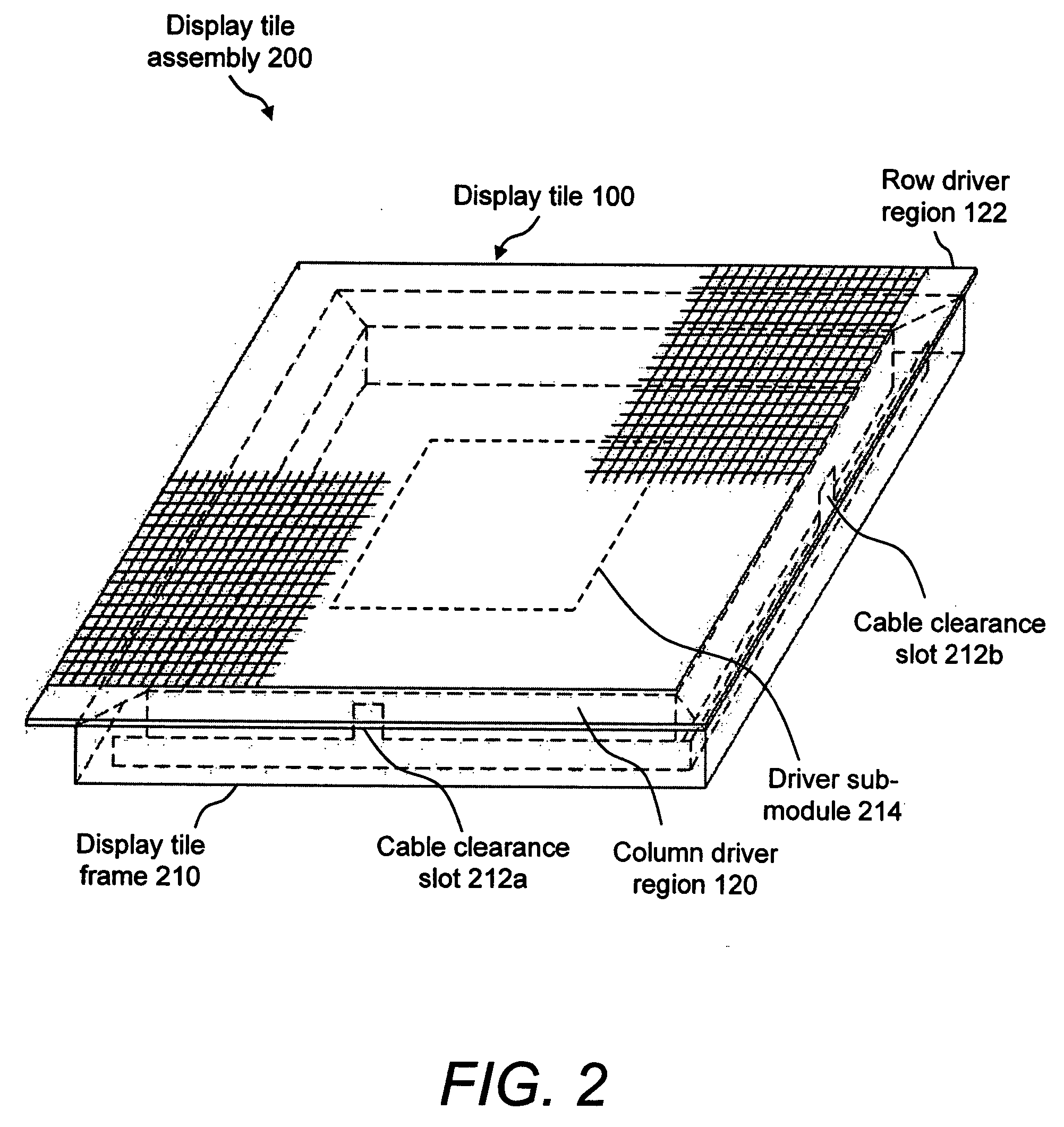
[0018]FIG. 1A illustrates a front view of a display tile 100 that has integrated column and row drivers. Display tile 100 is suitable for use in a modular flat-panel display in accordance with the invention. Display tile 100 is a thin (100-150 μm) flexible active matrix OLED display panel that is, for example, 10 to 12 inches square. Display tile 100 includes an active matrix region 110, which includes electronic circuitry for an array of light-emitting devices, such as OLEDs. Display tile 100 is bounded by a first edge 112, a second edge 114, a third edge 116, and a fourth edge 118. Display tile 100 further includes a column driver region 120 along first edge 112 and a row driver region 122 along second edge 114. Column driver region 120 includes integrated column drivers for receiving the display data. Row driver region 122 includes integrated row drivers for receiving the pulsed row signals, as is well known. The design of display tile 100 includes the integrated drivers, which a...


PUM


Abstract

A scalable tiled display assembly that includes an array of independently addressed active-matrix organic light-emitting diode (OLED) display tiles cabled to a central control module. Each display tile includes a frame, a driver sub-module, and a flat ribbon cable for connecting the driver sub-module to the display tile. Furthermore, column and row drivers are integrated within each display tile for improved performance and minimal external connections. The invention further includes a method of forming a scalable tiled display system that includes the steps of assembling a plurality of display tile assemblies, determining the viewable area of the display, assembling an array of display tile assemblies according to the desired viewable area, and activating the scalable tiled display system.

Description

FIELD OF THE INVENTION [0001] The present invention relates to a modular large-screen organic light-emitting diode (OLED) display. In particular, the invention relates to a scalable tiled display assembly for forming a large-area flat-panel display using modular display tiles. BACKGROUND OF THE INVENTION [0002] OLED technology incorporates organic luminescent materials that produce intense light of a variety of colors when sandwiched between electrodes and subjected to a DC electric current. These OLED structures can be combined into the picture elements, or pixels, that comprise a display. OLEDs are also useful in a variety of applications as discrete light-emitting devices or as the active element of light-emitting arrays or displays, such as flat-panel displays in watches, telephones, laptop computers, pagers, cellular phones, calculators, and the like. To date, the use of light-emitting arrays or displays has been largely limited to small-screen applications, such as those menti...

Claims


Application Information

Patent Timeline
IPC IPC(8): G09G5/00
CPCG06F3/1446G09G3/3208H01L27/3297H01L27/3293G09G2310/0221H10K59/18H10K59/131
Inventor BRODY, THOMAS P.MALMBERG, PAUL R.MARCANIO, JOSEPH A.
Owner ADVANTECH GLOBAL LTD
Learn More