
Method and apparatus for vaporizing a sterilant fluid using microwave energy

Inactive Publication Date: 2005-11-24
AMERICAN STERILIZER CO
View PDF27 Cites 11 Cited by
  • Summary
  • Abstract
  • Description
  • Claims
  • Application Information

AI Technical Summary

Benefits of technology

[0007] An advantage of the present invention is the provision of a vaporization method and apparatus that more efficiently vaporizes a sterilant fluid than a conventional thermal heating system.
[0008] Another advantage of the present invention is the provision of a vaporization method and apparatus that can be easily scaled to vaporize sterilant fluids of varying volumes.
[0009] A still further advantage of the present invention is the provision of a vaporization method and apparatus that can selectively excite molecules of a multicomponent sterilant fluid with microwave energy.
[0010] These and other advantages will become apparent from the following description of a preferred embodiment taken together with the accompanying drawings and the appended claims.

Problems solved by technology

For instance, considerable time may be needed in order to heat the hot surface to the desired temperature.
Furthermore, this type of vaporization system requires an energy consuming high wattage heater.

Method used


Image

  • Method and apparatus for vaporizing a sterilant fluid using microwave energy
  • Method and apparatus for vaporizing a sterilant fluid using microwave energy

Examples


Embodiment Construction

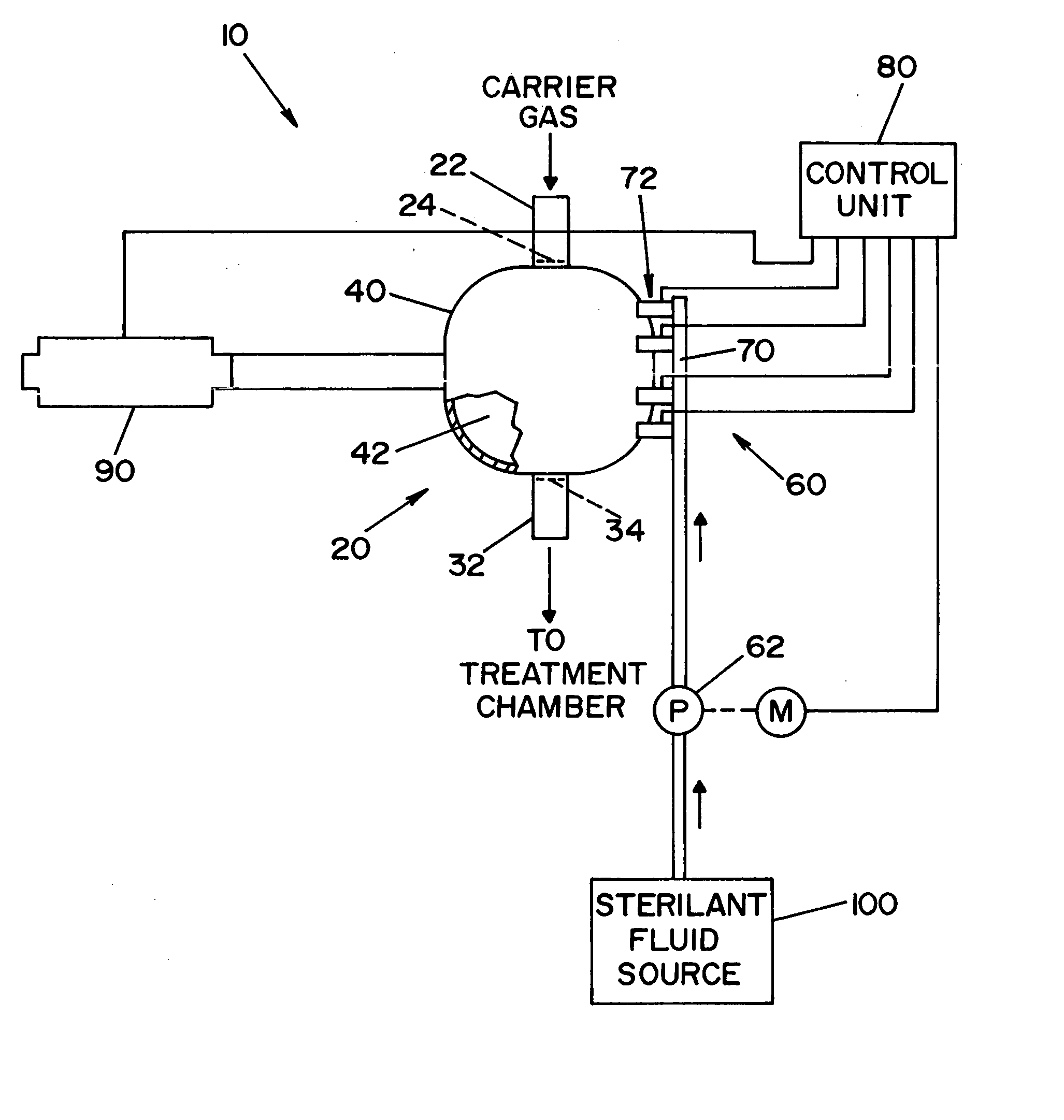
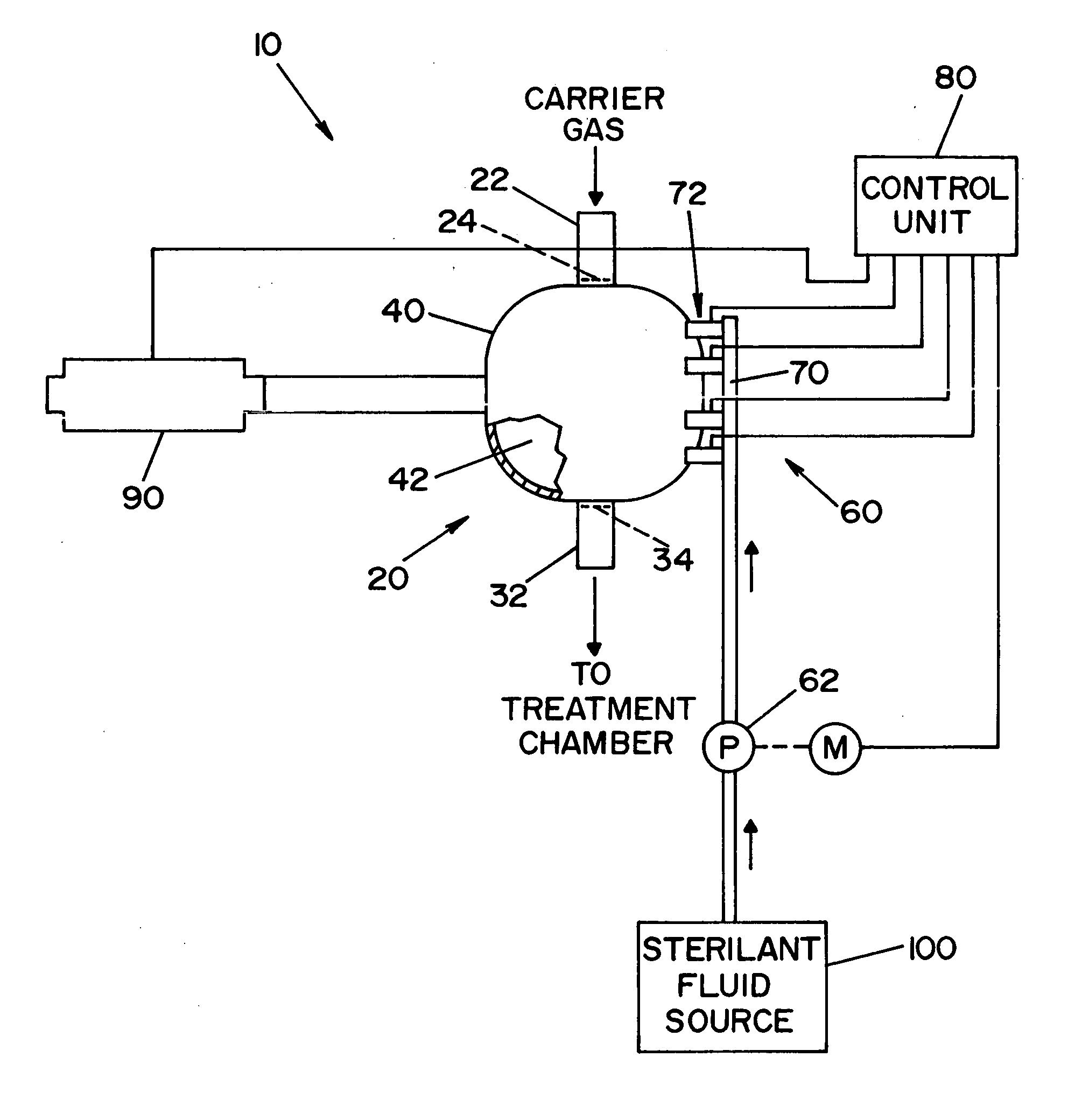
[0013] Referring now to the drawing wherein the showing is for the purpose of illustrating a preferred embodiment of the invention only and not for the purpose of limiting same, FIG. 1 shows a block diagram of a vaporization system 10 according to a preferred embodiment of the present invention. It should be understood that the terms sterilant (sterilization) and decontaminant (decontamination) are used interchangeably herein.

[0014] Vaporization system 10 is generally comprised of a vaporizer assembly 20, an injection system 60 and a microwave generator 90. Vaporizer assembly 20 includes an inlet conduit 22, an outlet conduit 32 and a housing 40. Housing 40 defines a vaporization chamber 42. Inlet conduit 22 provides a passageway for a carrier gas to enter vaporization chamber 42. Outlet conduit 32 provides a passageway for the carrier gas, and vaporized fluids to exit vaporization chamber 42, as will be described in detail below. Outlet conduit 32 is in fluid communication with a ...


PUM


Abstract

A method and apparatus for vaporizing a sterilant fluid using microwave energy. A sterilant fluid is atomized to produce a spray, mist or fog of sterilant fluid. The atomized sterilant fluid is then exposed to microwave energy produced by a microwave generator. Molecules of at least one chemical component of the sterilant fluid rotate in response to exposure to the microwave energy, thereby vaporizing the sterilant fluid.

Description

FIELD OF THE INVENTION [0001] The present invention relates generally to vaporization of a steriliant fluid, and more particularly to a method and apparatus for vaporizing a sterilant fluid using microwave energy. BACKGROUND OF THE INVENTION [0002] Articles are commonly sterilized or decontaminated by exposure to vaporized sterilants. In the prior art, it is well known to vaporize a liquid sterilant by metering liquid sterilant onto a hot surface. The hot surface heats the liquid sterilant, thereby producing a vaporized sterilant. This approach to vaporization has many drawbacks. For instance, considerable time may be needed in order to heat the hot surface to the desired temperature. Furthermore, this type of vaporization system requires an energy consuming high wattage heater. [0003] The present invention overcomes these and other drawbacks of the prior art, and provides a vaporization system that uses a source of microwave energy to vaporize a sterilant fluid in a vaporization ch...

Claims


Application Information

Patent Timeline
IPC IPC(8): A61L2/00A61L2/12A61L2/20A61L2/22A61L2/24
CPCA61L2/12A61L2/202A61L2202/11A61L2/22A61L2/24A61L2/208
Inventor VOYTEN, STANLEY M.BACIK, MICHAEL A.ADAMS, PETER R.CENTANNI, MICHAEL A.
Owner AMERICAN STERILIZER CO
Learn More