
Airborne platform

Inactive Publication Date: 2014-01-02
OMNIDEA
View PDF7 Cites 14 Cited by
  • Summary
  • Abstract
  • Description
  • Claims
  • Application Information

AI Technical Summary

Benefits of technology

The present invention provides a solution for creating large, modular airborne platforms that can be easily scaled up by adding more elements. The platform has envelopes with gas that provide buoyancy force, regardless of air motion. Scalability is achieved by adding extra lifting bodies or sets of lifting bodies to a common base structure for smaller or larger versions of the platform. These modular airborne platforms can have a significant impact on various applications such as surveillance, aerial photography, and search and rescue.

Problems solved by technology

Although non-rigid aerostats (blimps) can be built to arbitrarily large sizes without rigid structures of comparable dimension, their sole reliance on buoyancy for lift makes very large payloads unfeasible due to the huge volume of buoyant gas necessary and the limits of wind speeds to which it can be subjected before crashing by the dynamic behaviour induced by drag.
The most effective buoyant gases that can be used are helium, which is very expensive and hydrogen, which is highly flammable.
Therefore, handling a very large amount of either is always costly.
Regarding aerial cargo transport, it has been mostly limited to one of three aircraft types: fixed-wing freight aircraft, cargo helicopters and airships.
Fixed wing freight aircraft often have dimensional limitations (limited cargo space inside the fuselage) that prohibit the transport of payloads with very large dimensions or dimensional proportions too distinct from those of the aircraft's fuselage.
Additionally, pure fixed wing aircraft cannot achieve vertical take-off and landing, or operate in confined spaces
However, cargo helicopters retain the range limitations typical of rotorcraft and cannot be practically scaled up to very large dimensions.
Although they can carry bulky payloads externally, scaling them up raises the aforementioned problems related to envelope size.
This means that there are no means through which control forces applied at different points of the aircraft can be generated using the same mechanism that generates the aerodynamic lifting force.

Method used


Image

  • Airborne platform
  • Airborne platform
  • Airborne platform

Examples


Embodiment Construction

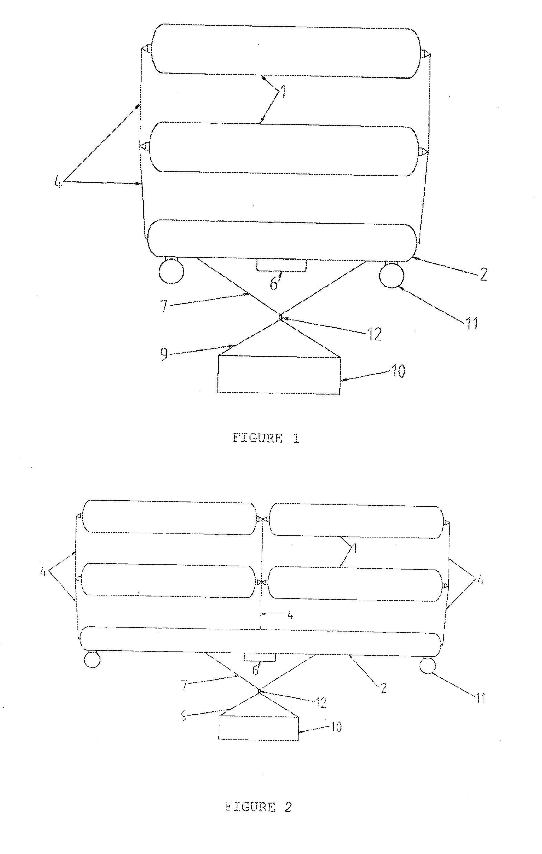
[0033]Of the aforementioned components that are part of the invention systems, the most important are:[0034]the lifting bodies (1) of the aerodynamic system;[0035]the anchoring modules (or anchoring bodies) (2, 3) of the structural system (that hold compressive loads (it should be noted that anchoring modules can also be lifting bodies);[0036]the various sets of structural elements (4,7,8,9,14) that connect the various platform components and are mainly under traction stress (notwithstanding bending or compression) also belonging to the structural system;[0037]the components that are part of the interface system, which include the components for transmitting torque and rotation to the lifting bodies (1), which include parts from the both the control, and the structural system.

[0038]Although not limitative, in preferred embodiments, both the lifting bodies (1) and the anchoring modules (2,3) are slender cylinders, total or partially inflated with buoyant gas. At least the upper most ...


PUM


Abstract

The invention pertains to aeronautical engineering and consists of an airborne platform that can be built to large sizes without requiring a rigid structure of comparable dimensions and which uses both buoyancy and the aerodynamic Magnus effect for lift. The aerodynamic lift is generated in lifting bodies (1), which also contain buoyant gas. The lifting bodies (1) are stacked in a column, at the bottom of which there is a structural anchoring module (2) which also contains buoyant gas. The lifting bodies (1) and anchoring modules (2) are connected by slender structural elements which, when taken together as a whole form a non-rigid assembly. The platform may be tethered or configured as an aircraft, for which purpose other features may be added, such as a propulsion system (11), a crew gondola (6), cables to (7) and from (8) a swivel (12) and a payload (10) connected to said cables.

Description

FIELD OF THE INVENTION[0001]The present invention relates to the field of Aeronautical Engineering and consists of an airborne platform that can be built to arbitrarily large sizes without requiring rigid structures of a dimension comparable to that of the platform, and uses a combination of buoyancy and aerodynamic lift via the Magnus effect in order to stay aloft. This platform can be used as an aircraft (aerial vehicle), or it can be tethered to fulfil roles that are suited to static platforms. Possible applications for this airborne platform include (but are not limited to) cargo and passenger transport, forest fire fighting, advertising, aerial photography, video recording and surveillance, telecommunications and wind energy harnessing.BACKGROUND OF THE INVENTIONCited Documents[0002]Patent WO2004 / 012992A2, R. Mondale, 12 / Feb. / 2004;[0003]U.S. Pat. No. 4,366,936A, F. D. Ferguson, 4 / Jan. / 1983;[0004]Patent WO2007 / 139412A1, T. Pardal, 6 / Dec. / 2007.[0005]Airborne platforms can either ...

Claims


Application Information

Patent Timeline
IPC IPC(8): B64B1/02
CPCB64B1/02B64B1/40Y02T70/5236B64U10/60B64C39/022B64C39/00B64B1/66
Inventor COSTA DUARTE PARDAL, TIAGOMARQUES DOS SANTOS SILVA, PEDRO MIGUEL
Owner OMNIDEA
Learn More