
Cantilever and straddle x-ray tube configurations for a rotating anode with vacuum transition chambers

a technology of transition chamber and rotating anode, which is applied in the direction of x-ray tube gas filling, electric discharge tube, electrical apparatus, etc., can solve the problems of high voltage instability, high voltage vacuum degradation, and inability to utilize grease or oil lubricated bearings

Inactive Publication Date: 2006-02-16
GE MEDICAL SYST GLOBAL TECH CO LLC
View PDF5 Cites 14 Cited by
  • Summary
  • Abstract
  • Description
  • Claims
  • Application Information

AI Technical Summary

Benefits of technology

[0008] The present invention provides an imaging tube assembly for a diagnostic imaging system. The imaging tube assembly includes an insert that has a vacuum chamber. An anode resides within the vacuum chamber and rotates on a shaft via one or more bearings. In one embodiment, a seal resides between the insert and the shaft. The seal prevents the passage of atmospheric gasses into the vacuum chamber. In another embodiment, a pressure transition chamber encases a portion of the seal and is coupled to the insert and the shaft. The pressure transition chamber has a middle pressure approximately in between an internal vacuum level pressure present in the vacuum chamber and atmospheric pressure.
[0009] The embodiments of the present invention provide several advantages. One such advantage is the provision of a rotating anode internal to a stationary insert. Non-rotation of the insert allows for the usage of a motor with less output power. Lower output power allows for usage of a smaller and less costly motor that produces a smaller amount of heat. Usage of a smaller motor increases the available space within a CT system.
[0010] Another advantage provided by an embodiment of the present invention is the provision of providing a rotating anode with minimal space between the anode and the cathode. The reduced anode / cathode spacing allows for improved focal spot control, which tends to provide smaller and better shaped focal spots. Improved focal spot size and shape provides improved image quality and visualization of small anatomy.
[0011] Yet another advantage provided by an embodiment of the present invention, is the provision of directly cooling an insert with a coolant, such as water or glycol. This simplifies the CT system and eliminates the need for an oil bath and other related components. The elimination of an oil bath aids in satisfying environmental, health, and safety concerns normally attributed with an x-ray system.
[0012] Still yet another advantage provided by an embodiment of the present invention, is the provision of using pressure transition chambers. The pressure transition chambers ease the transition in pressure between the vacuum chamber of an x-ray tube and external or room air, which increases the operating life of the x-ray tube and related components.
[0013] Furthermore, the above-described advantages separately and in combination provide improved x-ray tube performance, reliability, and allow for decreased x-ray tube design cycle times.

Problems solved by technology

Although the use of bearing grease may allow for increased load on the bearing, since the bearing is inside the high voltage vacuum of the x-ray tube, grease or oil lubricated bearings cannot be utilized.
Outgassing from the grease or oil leads to the degradation of the high voltage vacuum.
This degradation causes high voltage instability and improper operation of the x-ray tube and can render the x-ray tube inoperable.
Also, the use of silver or lead as a lubrication on the bearings is no longer able to sustain the required loads for adequate x-ray tube life.
This method of cooling the rotating anode in and of itself is also inadequate for increased gantry rotating speeds.
The rotating frame tube design is limited in peak power and requires a large motor for rotation of the insert, which increases heat generation into a gantry and limits the x-ray tube thermal performance.
The use of this long beam path can result in focal spot irregularities.
These irregularities include a highly non-uniform intensity or unstable focus of the x-ray beam.
The irregularities increase with an increase in target size and negatively affect image clarity and usefulness.

Method used


Image

  • Cantilever and straddle x-ray tube configurations for a rotating anode with vacuum transition chambers
  • Cantilever and straddle x-ray tube configurations for a rotating anode with vacuum transition chambers
  • Cantilever and straddle x-ray tube configurations for a rotating anode with vacuum transition chambers

Examples


Embodiment Construction

[0023] In the following Figures the same reference numerals will be used to refer to the same components. While the present invention is described with respect to a system for sealing and cooling a rotating anode and associated vacuum vessel, the present invention may be adapted and applied to various systems including computed tomography (CT) systems, x-ray systems, Mammography systems, Vascular systems, Surgical-C systems, Radiographic (RAD) systems, RAD and Fluoroscopy Systems, and mixed modalities, such as CT-positron emission tomography (PET) or CT-Nuclear.

[0024] In the following description, various operating parameters and components are described for one constructed embodiment. These specific parameters and components are included as examples and are not meant to be limiting.

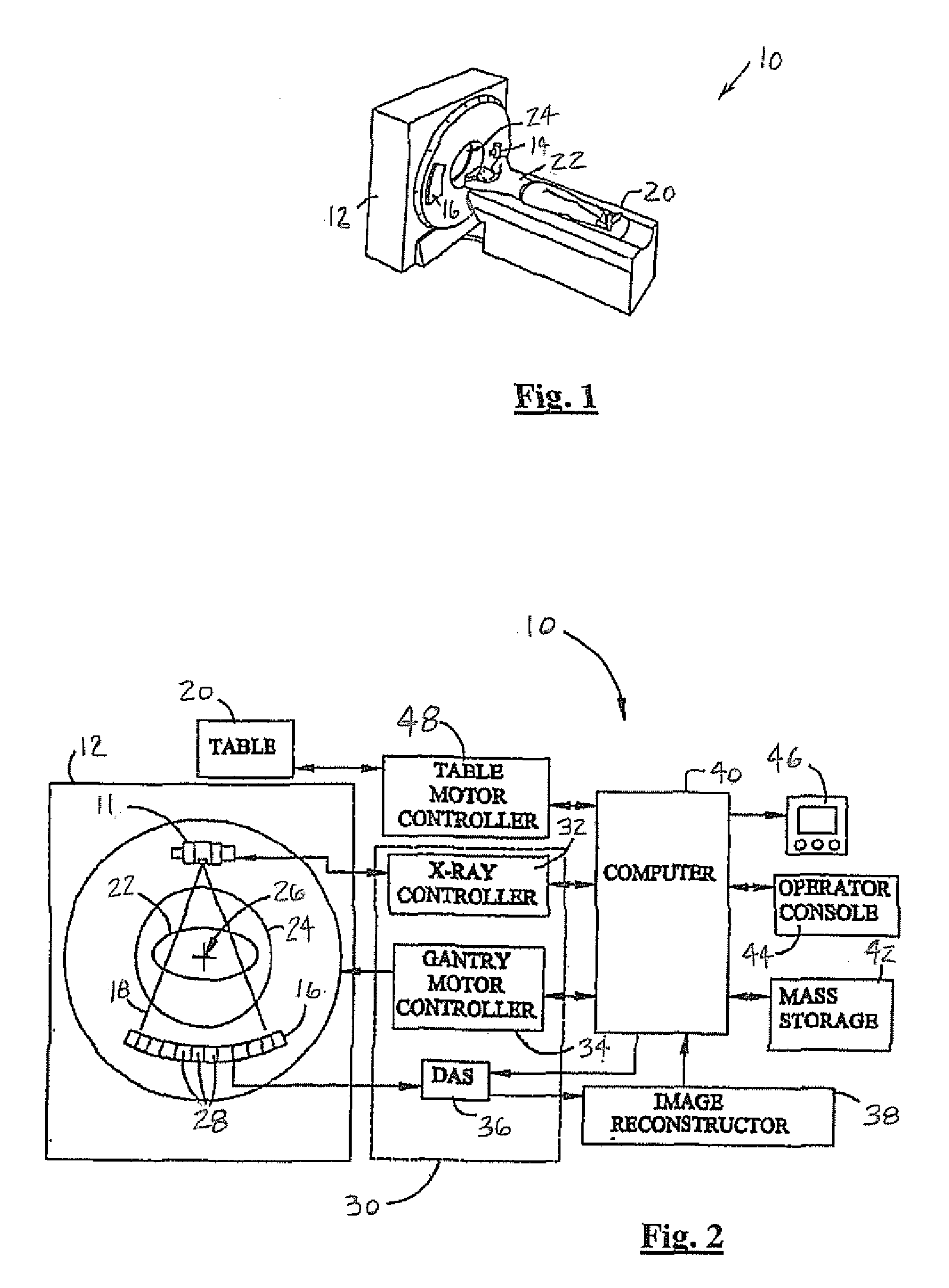
[0025] Referring now to FIGS. 1 and 2, perspective and schematic block diagrammatic views of a CT imaging system 10 incorporating an x-ray source or x-ray tube assembly 11 are shown in accordance with ...


PUM


Abstract

An imaging tube assembly (11) for a computed tomography (CT) system (10) includes an insert (60) that has a vacuum chamber (72). An anode (58) resides within the vacuum chamber (72) and rotates on a shaft (66) via one or more bearing (70). In one embodiment, a seal (52) resides between the insert (60) and the shaft (66). The seal (52) prevents the passage of a gas (80) into the vacuum chamber (72). In another embodiment, a pressure transition chamber (104) is coupled to an insert (60″) and a shaft (66″). The pressure transition chamber (104) has an associated middle fluid pressure that is between an internal fluid pressure of the vacuum chamber (104) and an external fluid pressure of said insert (60″).

Description

BACKGROUND OF INVENTION [0001] The present invention relates generally to computed tomography (CT) imaging systems. More particularly, the present invention relates to a system for sealing and cooling a rotating anode and associated vacuum vessel. [0002] A CT imaging system typically includes a gantry that rotates at various speeds in order to create a 360° image. The gantry contains an x-ray source, such as an x-ray tube that generates x-rays by bombardment of an anode by a high energy electron beam from a cathode physically separated from the anode by a vacuum gap. The anode has a target that is coupled to a shaft, which rotates on a pair of anode bearings. X-rays are emitted from the target and are projected in the form of a fan-shaped beam, which is collimated to lie within an X-Y plane of a Cartesian coordinate system, generally referred to as the “imaging plane”. The x-ray beam passes through the object being imaged, such as a patient. The beam, after being attenuated by the o...

Claims


Application Information

Patent Timeline
Patent Type & Authority Applications(United States)
IPC IPC(8): H01J35/10H01J35/28
CPCH01J35/10
Inventor UNGER, CHRISTOPHER D.HALLMAN, DARREN L.SMITH, WALTERSIMPSON, JAMES E.
Owner GE MEDICAL SYST GLOBAL TECH CO LLC
Learn More