Optical element holder, exposure apparatus, and device fabricating method
a technology of exposure apparatus and optical element, applied in the field of holding apparatus, can solve the problems of deterioration of imaging performance, no glass material exists for the wavelength range of euv light, and difficulty in using a refraction element or lens used for visible light and ultraviolet light,
- Summary
- Abstract
- Description
- Claims
- Application Information
AI Technical Summary
Benefits of technology
Problems solved by technology
Method used
Image
Examples
first embodiment
The First Embodiment
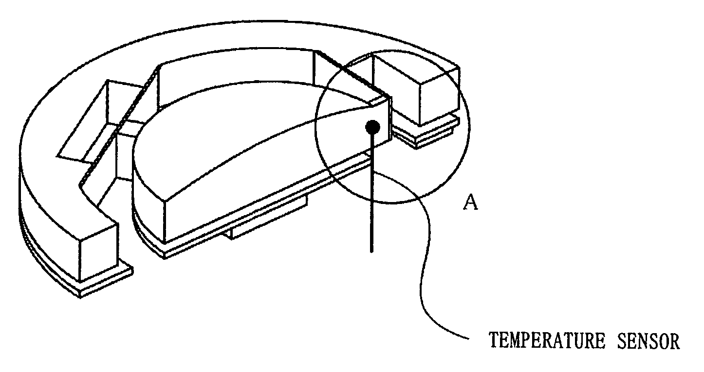
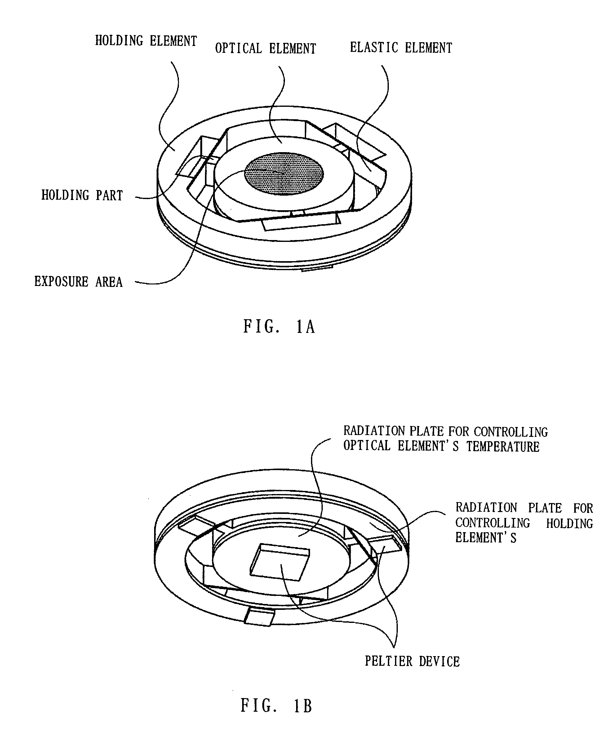
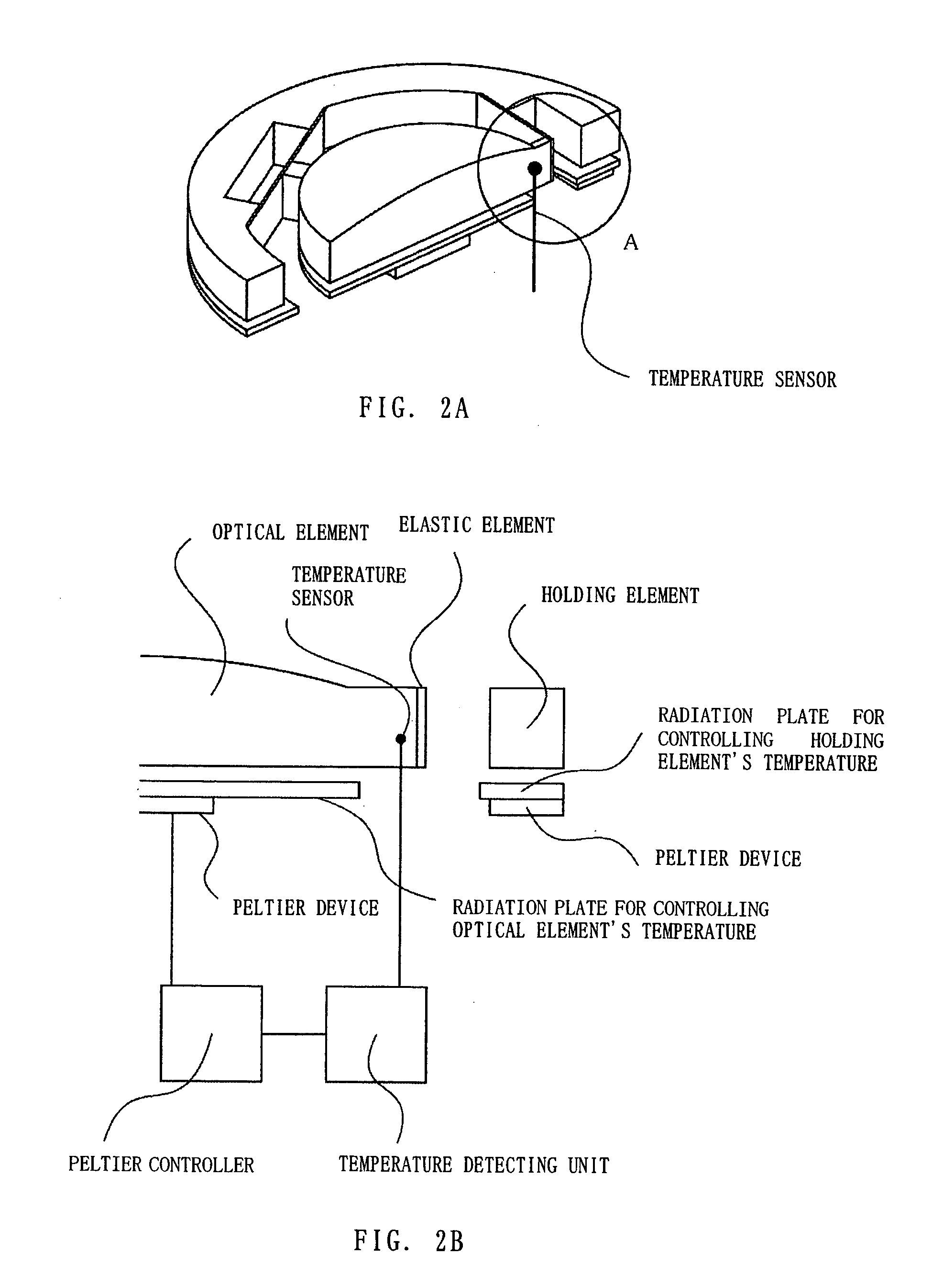
[0032]FIG. 1 and FIG. 2 show an optical element holder of the first embodiment according to the present invention.
[0033]FIG. 1A is a view from an exposure area side, FIG. 1B is a bottom view, FIG. 2A is a sectional view along the optical element's center, and FIG. 2B is an enlarged view of portion A in FIG. 2A.
[0034] The optical element is engaged via a holding part to an elastic element that is fixed to a holding element. The holding part may be part of the optical element or another element provided to the optical element unitedly. The holding part is preferably united to the optical element mechanically or adhered to the optical element by adhesive. However, it may be nearly united, for example, it may have a structure that is approximately united to the optical element due to gravity and friction by the gravity. The holding part and the elastic element may be connected mechanically or adhered by the adhesive. However, an adhesive with little outgas in vacuu...
second embodiment
The Second Embodiment
[0043]FIG. 3 shows an optical element holder of the second embodiment according to the present invention. FIG. 3A is a sectional view at a center of the optical element. FIG. 3B is an enlarged view of portion B shown in FIG. 3A. The radiation plate for controlling the optical element's temperature and the Peltier device are not shown but have the same functions as in the first embodiment.
[0044] Instead of a radiation plate as in the first embodiment, this embodiment uses a heater for controlling the holding element's temperature. The heater is arranged on an elastic element side, near a connection part, of the holding part and the elastic element (the holding element). Moreover, temperature sensors are arranged on both the elastic element side and on a holding part side, near the connection part, of the holding part and the elastic element.
[0045] Because this embodiment uses the temperature sensors to detect the temperatures of two portions in both sides of th...
third embodiment
The Third Embodiment
[0047]FIG. 4 shows an optical element holder of the third embodiment according to the present invention. FIG. 4A shows the holding element which holds the optical element via a linear motor without contact. FIG. 4B is a developmental view of the optical element and the holding element shown in FIG. 4A.
[0048] In this embodiment, the holding element holds the optical element via the linear motor without contact. A cooling pipe, provided in the holding element, maintains the holding element at constant temperature.
[0049] The linear motor uses needles and stators in pair. In this embodiment, the linear motors uses two pairs of needles and stators for the x direction, two pairs for the y direction, and three pairs for the z direction. Relative to the holding element, this can drive the optical element in six directions along the x, y, and z axes and along the rotational directions around the x, y, and z axes.
[0050] Heat generated by the optical element from absorpt...
PUM
 Abstract
Description
Claims
Application Information
 - R&D
- Intellectual Property
- Life Sciences
- Materials
- Tech Scout
- Unparalleled Data Quality
- Higher Quality Content
- 60% Fewer Hallucinations
Browse by: Latest US Patents, China's latest patents, Technical Efficacy Thesaurus, Application Domain, Technology Topic, Popular Technical Reports.
© 2025 PatSnap. All rights reserved.Legal|Privacy policy|Modern Slavery Act Transparency Statement|Sitemap|About US| Contact US: help@patsnap.com


