Exposure head and image forming apparatus
- Summary
- Abstract
- Description
- Claims
- Application Information
AI Technical Summary
Benefits of technology
Problems solved by technology
Method used
Image
Examples
first embodiment
B-1. First Embodiment
[0050]FIG. 3 is a diagram illustrating an example of an image forming apparatus to which the invention can be applied. FIG. 4 is a block diagram of the electrical structure of the image forming apparatus illustrated in FIG. 3. The image forming apparatus can selectively perform a color mode or a monochrome mode. In the color mode, a color image is formed by overlaying toners of four colors: black (K), cyan (C), magenta (M), and yellow (Y). In the monochrome mode, a monochrome image is formed using only the black (K) toner. FIG. 3 illustrates the image forming apparatus when performing the color mode. In the image forming apparatus, when an image forming command is supplied by an external apparatus such as a host computer to a main controller MC, which includes a CPU and a memory, the main controller MC supplies a control signal and the like to an engine controller EC and supplies video data VD corresponding to the image forming command to a head controller HC. A...
second embodiment
B-2. Second Embodiment
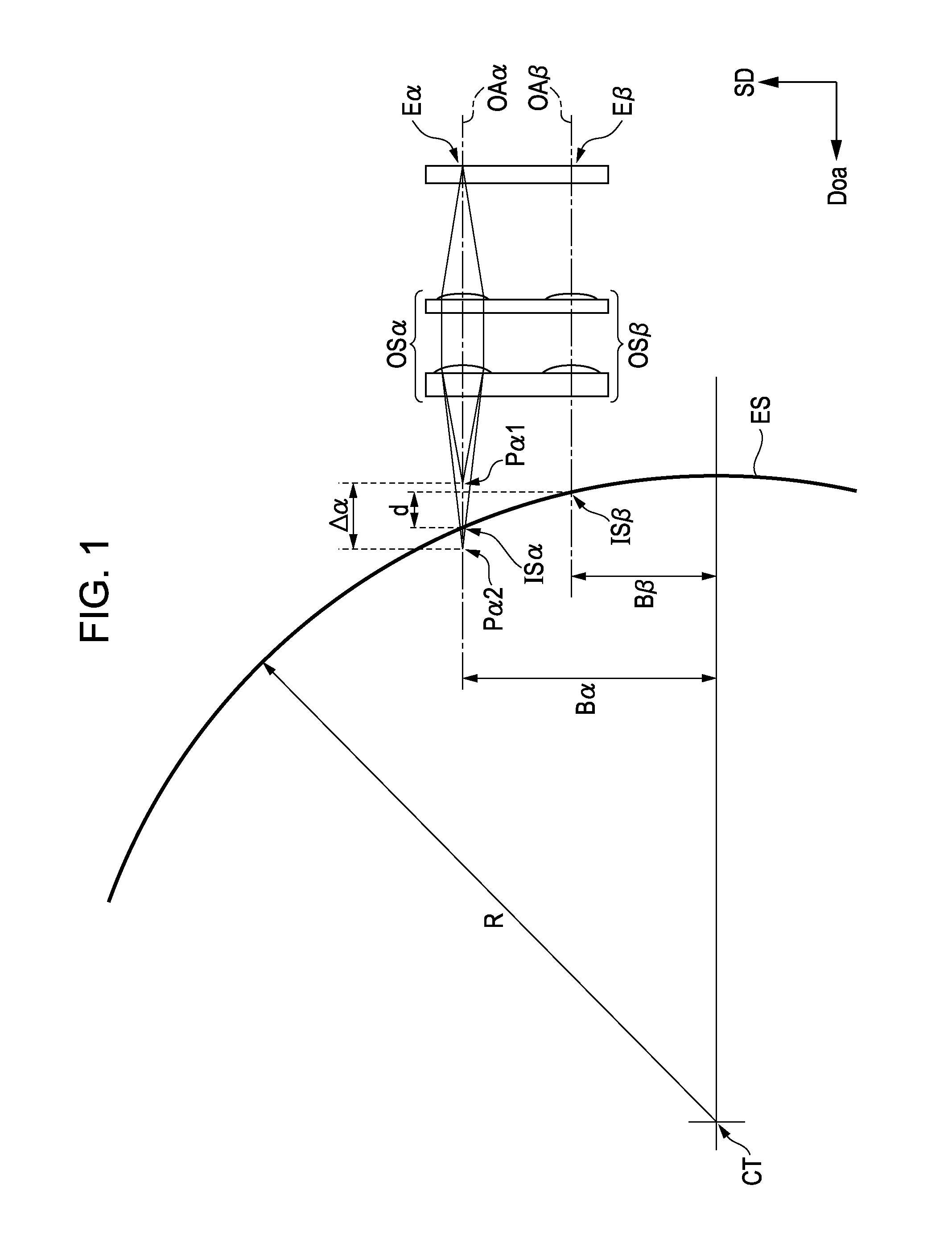
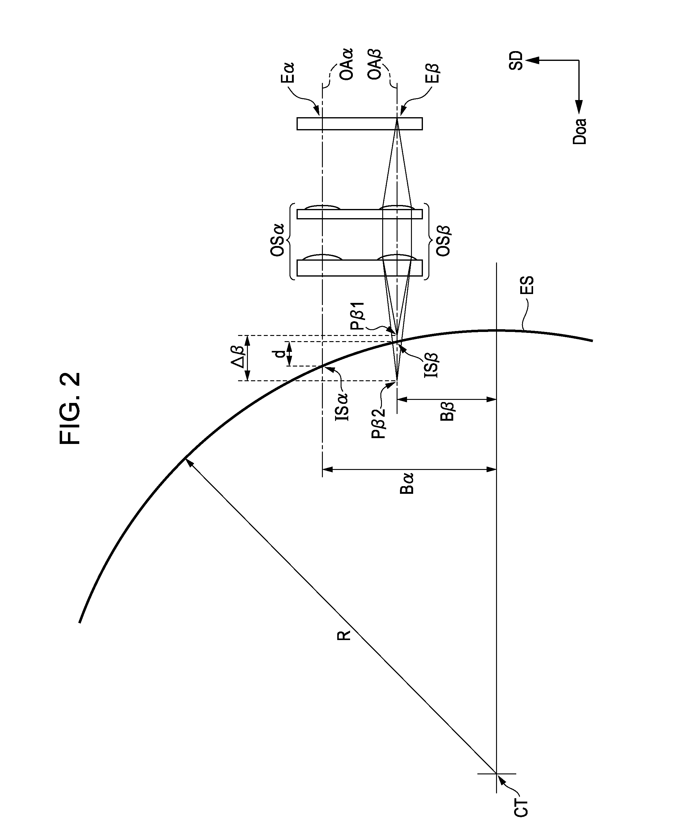
[0087]In the first embodiment, the imaging position of the light having the wavelength λ1 and the imaging position of the light having the wavelength λ2 are separated from each other by the distance Δ in the optical axis direction Doa. In other words, the distance Δ between the first imaging plane IP1 and the second imaging plane IP2 in the optical axis direction Doa is equal to or larger than the distance d, so that the difference between the sizes of the spots SP formed by the optical systems is suppressed. However, if the distance Δ is too large, aberration of the spot SP becomes large and an imaging performance deteriorates, so that exposure may become uneven and the resolution may decrease. Therefore, a second embodiment has the following structure, in addition to the structure the same as that of the first embodiment. Needless to say, the second embodiment has the same advantage as that of the first embodiment, because the second embodiment include the st...
third embodiment
B-3. Third Embodiment
[0090]FIG. 11 is a diagram illustrating the structure of a line head of a third embodiment, viewed from the main scanning direction MD. The third embodiment differs from the first embodiment mainly in that the optical axis OAb of the middle optical system constituted by LS1b and LS2b is off the center of curvature CT21 of the photosensitive drum 21. As a result, a relationship Ba>Bc>Bb (Ba is the largest and Bb is the smallest) is satisfied, where Ba is the distance between the center of curvature CT21 and the optical axis OAa of the upstream optical system, Bb is the distance between the center of curvature CT21 and the optical axis OAb of the middle optical system, and Bc is the distance between the center of curvature CT21 and the optical axis OAc of the downstream optical system.
[0091]With this structure, there is a large displacement dmx between the intersection points Ia and Ib in the optical axis direction Doa, where the intersection point Ia is a point a...
PUM
 Abstract
Description
Claims
Application Information
 - R&D Engineer
- R&D Manager
- IP Professional
- Industry Leading Data Capabilities
- Powerful AI technology
- Patent DNA Extraction
Browse by: Latest US Patents, China's latest patents, Technical Efficacy Thesaurus, Application Domain, Technology Topic, Popular Technical Reports.
© 2024 PatSnap. All rights reserved.Legal|Privacy policy|Modern Slavery Act Transparency Statement|Sitemap|About US| Contact US: help@patsnap.com


