
Broadband antenna arrangement

Active Publication Date: 2006-02-16
HUBERSUHNER AG
View PDF4 Cites 5 Cited by
  • Summary
  • Abstract
  • Description
  • Claims
  • Application Information

AI Technical Summary

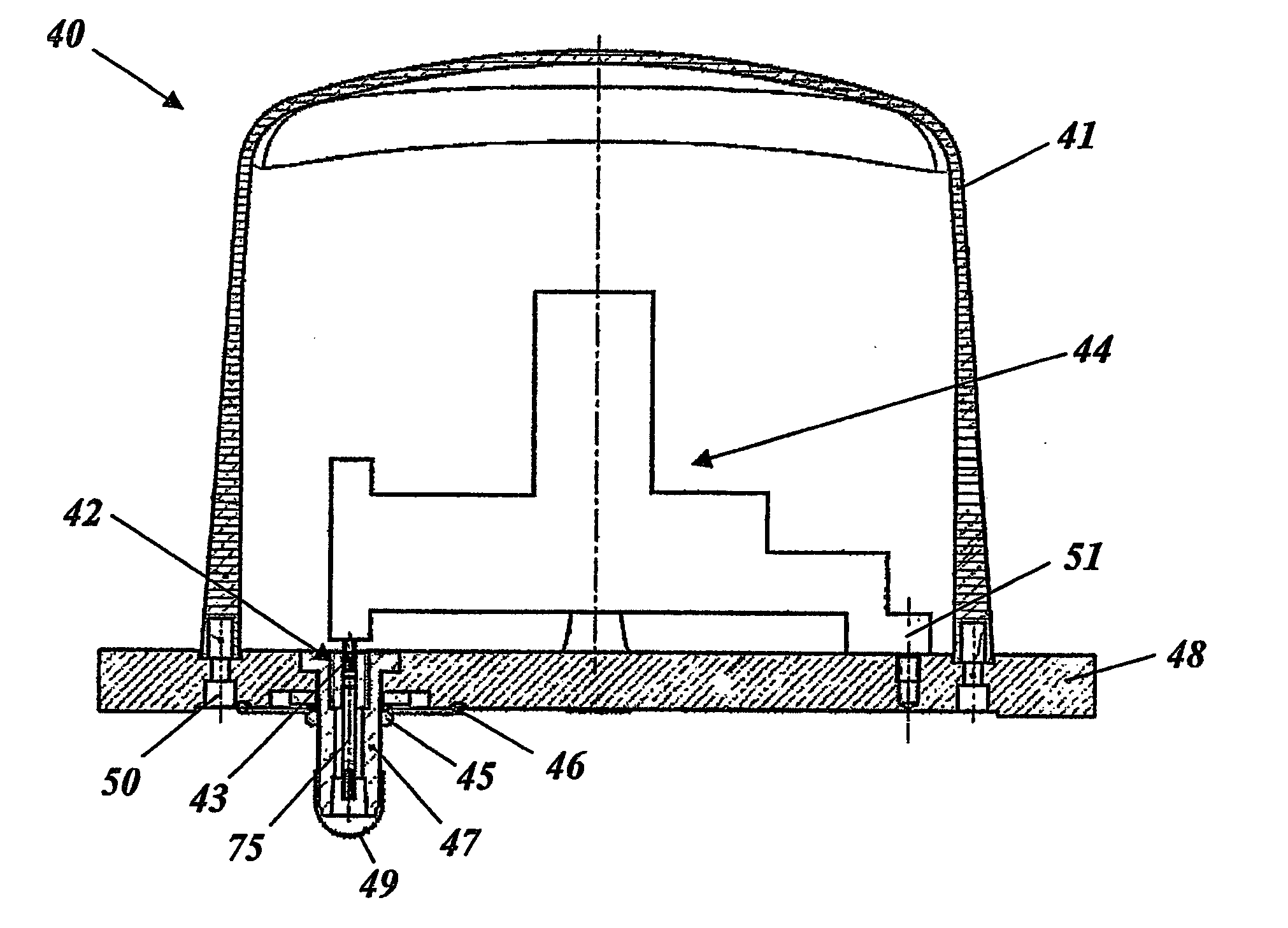
Benefits of technology

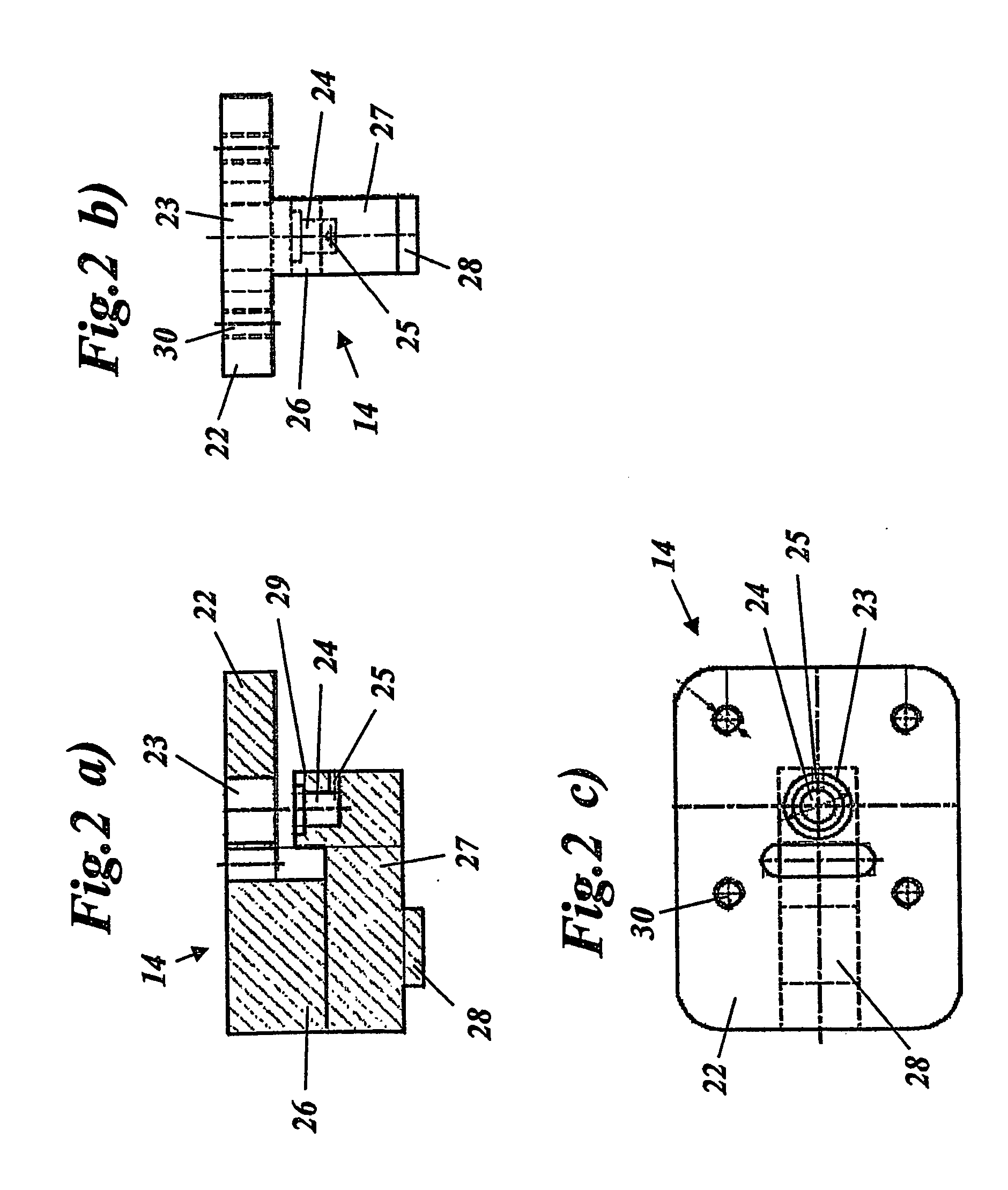
[0010] According to a first preferred embodiment, a high degree of mechanical robustness and a high current carrying capacity as well as simplified assembly are achieved, because of several combined features: (1) the antenna element is in the form of a solid metal plate which has a constant thickness transversely with respect to the longitudinal direction and is composed of aluminum or an aluminum alloy; (2) the antenna element has a foot at the first end; (3) the antenna element is attached to the base plate by the foot; and (4) the foot has at least one threaded hole or attachment hole, through which the foot is screwed to the base plate.
[0011] The design and assembly are particularly simple and functionally reliable if, according to a second preferred embodiment, a coaxial plug connector which is at a right angle to the base plate, and in particular is in the form of a connecting socket, is arranged on the lower face of the base plate in the area of the feed point, with its outer conductor being electrically conductively connected to the base plate and its inner conductor being electrically conductively connected through an opening in the base plate to the feed point of the antenna element. It is also preferred that the connection between the feed point and the inner conductor of the coaxial plug connector is designed to be detachable, in which case an electrically conductive connecting pin which projects downwards at a right angle to the base plate is arranged at the feed point of the antenna element and fits in a socket which is fitted to the inner conductor of the coaxial plug connector.
[0012] The connecting pin may in this case be integrally formed on the antenna element. It is then also machined out during the mechanical machining of the antenna element. However, it may also be in the form of a separate push-in pin, and may be pushed into a corresponding opening in the antenna element. This has the advantage that the connecting pin may be composed of a different material, which is optimized for making contact, and may be produced more easily.
[0013] In order to protect the antenna element against damaging environmental influences, it is advantageous for the antenna element to be covered on the outside by a removable shroud, which is detachably connected, in particular screwed, to the base plate.

Problems solved by technology

Frequently the space available for the antennas is restricted (in the case of portable radio appliances, for example).

Method used


Image

  • Broadband antenna arrangement
  • Broadband antenna arrangement
  • Broadband antenna arrangement

Examples


Embodiment Construction

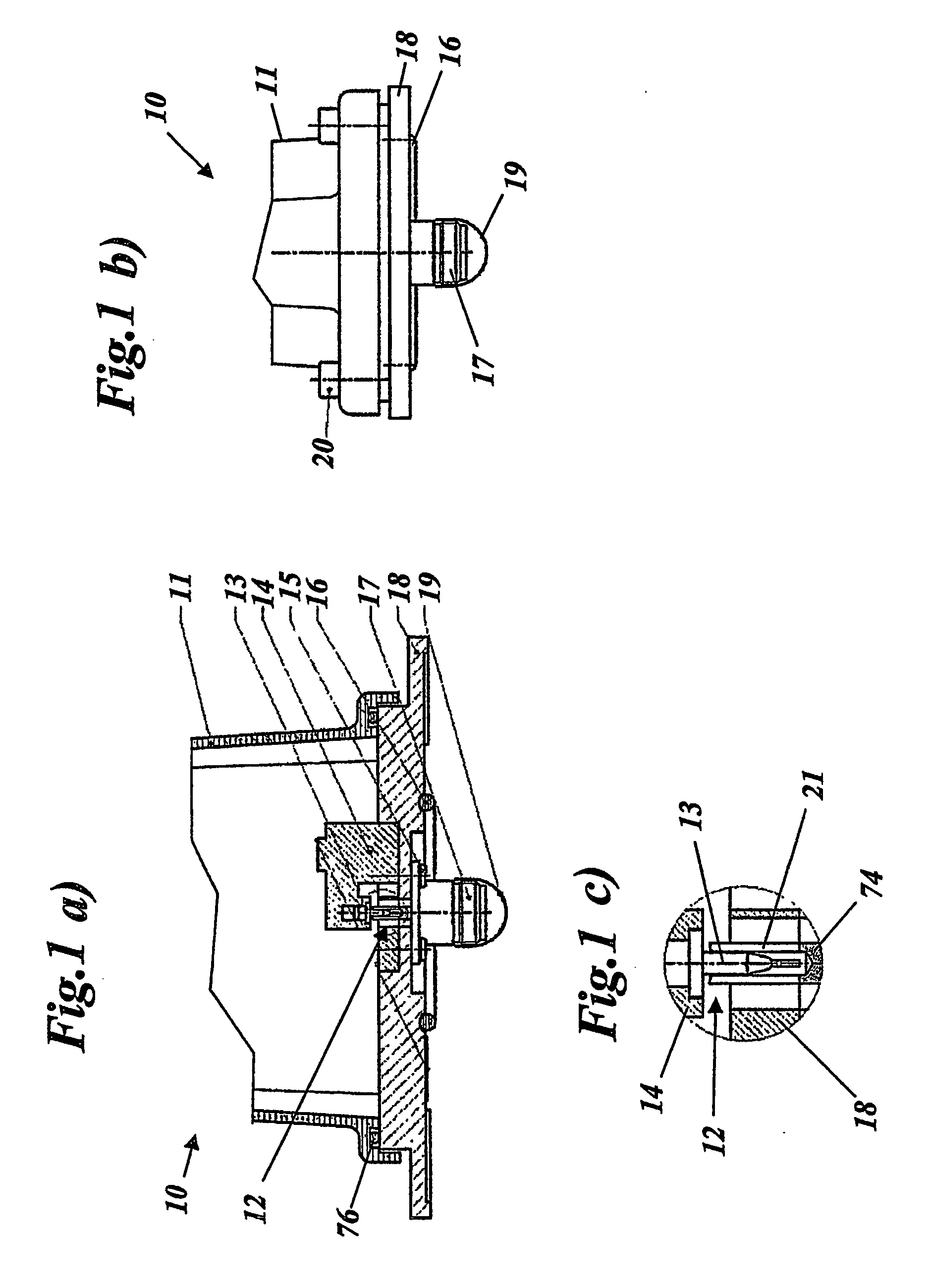
[0026] FIGS. 1(a)-1(c) show different views of a first embodiment of an antenna arrangement according to the present invention. FIG. 1(a) shows a longitudinal cross section of the antenna arrangement 10, which is formed on an electrically conductive base plate 18 and is covered by a shroud 11 in the form of a cup. The shroud 11 is preferably composed of a fiber-reinforced plastic and is screwed to the base plate 18 by means of four screws 20, which are screwed into the corresponding threaded holes 34 (FIG. 3) in the base plate. In the first embodiment, the shroud 11 has a flange-like edge with a circumferential groove, in which a sealing ring 76 is inserted to improve the sealing of the internal area from the external area.

[0027] As can be seen from FIGS. 1(a) and 3, the essentially rectangular base plate 18 has a raised mounting platform 32 in the central area, adjacent to which are two attachment flanges 31, 31′ on the transverse faces with two attachment holes 33 provided at eac...


PUM


Abstract

The invention relates to a compact and robust broadband antenna, for the frequency range from about 800 MHz up to 9 GHz, in particular, for use on railways. The antenna includes a monopole antenna element, extending in a longitudinal direction essentially parallel to and at a distance above a planar electrically-conducting base plate, between two opposing ends of the antenna element. The antenna element is electrically connected to the base plate at the first end thereof and is insulated from the base plate at the second end thereof, creating an injection point by means of which the antenna element may be connected to a device operating at high frequency.

Description

CROSS REFERENCE TO RELATED APPLICATION [0001] This application is a continuation of International Application Serial No. PCT / CH03 / 000275, having an international filing date of Apr. 28, 2003, which designated the United States, the entirety of which is incorporated herein by reference.FIELD OF THE INVENTION [0002] The present invention relates to the field of antenna technology. It relates in particular to a physically compact and mechanically robust monopole broadband vehicle antenna capable of operating in the frequency range between about 800 MHz and 9 GHz, and which has a sufficiently high current carrying capacity to be suitable for specific use in high current applications (on board trains, for example). BACKGROUND OF THE INVENTION [0003] The geometric dimensions of antennas are closely related to the wavelength of the waves which are intended to be emitted or received via the antennas. Frequently the space available for the antennas is restricted (in the case of portable radi...

Claims


Application Information

Patent Timeline
IPC IPC(8): H01Q1/32H01Q1/42H01Q5/00H01Q5/371H01Q9/40H01Q9/42
CPCB61L15/0027H01Q1/3216H01Q5/371H01Q9/40H01Q9/42H01Q1/42
Inventor DEJEAN, CEDRIC
Owner HUBERSUHNER AG
Learn More