
Microwave-sending device

a microwave and transmission device technology, applied in waveguides, liquid/fluent solid measurements, antennas, etc., can solve the problems of increased production and assembly effort, increase costs, etc., and achieve the effects of reducing costs, reducing construction complexity, and reducing production and assembly

Active Publication Date: 2013-03-07
KROHNE MESSTECHNICK GMBH & CO KG
View PDF13 Cites 6 Cited by
  • Summary
  • Abstract
  • Description
  • Claims
  • Application Information

AI Technical Summary

Benefits of technology

The present invention provides a microwave-sending device with simplified construction, reduced production and assembly costs, while maintaining high mechanical robustness and stability. The device has a casting that securely attaches the electronics, wave coupler, and waveguide together, using materials that have sufficient flowability and suitable mechanical, electrical, thermal, and chemical characteristics. The casting material can be any of a variety of suitable materials, such as casted epoxy or casted silicone. The use of the casting simplifies the mechanical construction process and reduces the need for additional devices like fixtures and seals, lowering production and assembly costs. The casting also serves as protection against environmental effects and provides ignition protection. Overall, the microwave-sending device of the invention meets these technical requirements while remaining easy to use and economical.

Problems solved by technology

The fixtures for the components, and the closure having the seal and the fixture, increase the constructional complexity as well as the production and assembly effort, which then increase costs.

Method used


Image

  • Microwave-sending device
  • Microwave-sending device
  • Microwave-sending device

Examples


Embodiment Construction

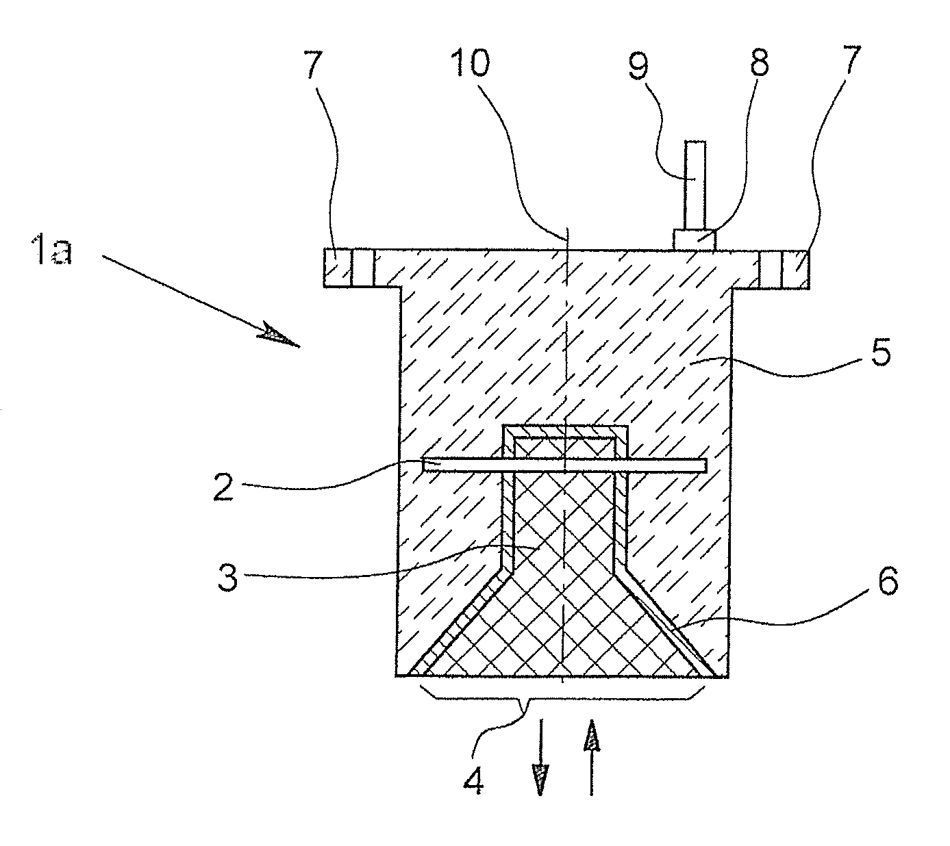
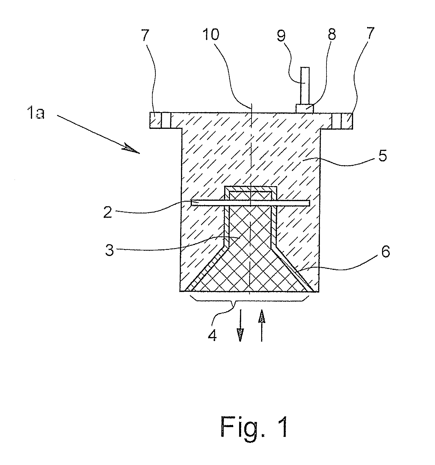
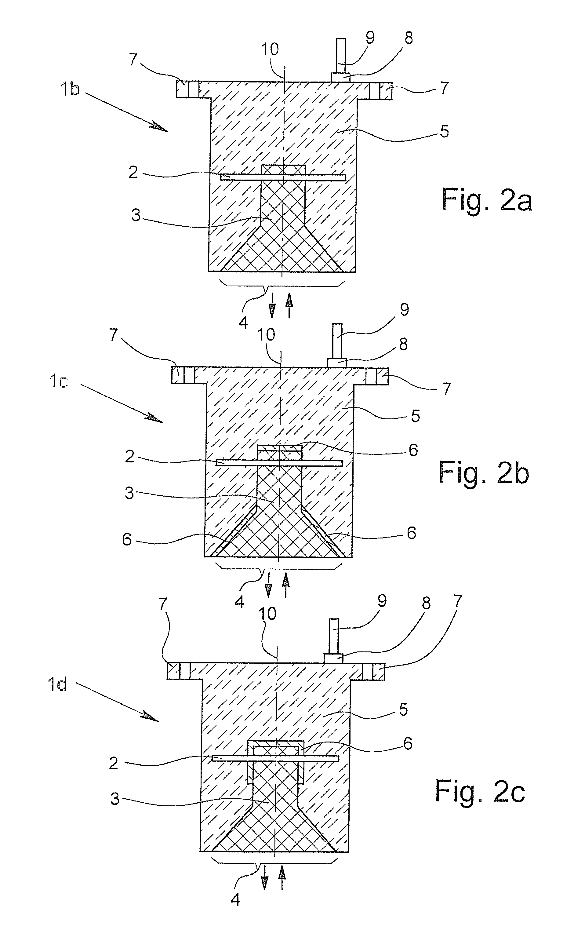
[0023]Microwave-sending devices 1a-1g according to the invention are shown in FIGS. 1 to 5, which have electronics 2, a wave coupler (not shown), a waveguide 3 and a wave-emitting section 4. A casting 5 mechanically affixes the electronics 2, the waveguide 3, and the wave coupler arranged on a carrier of the electronics in a robust manner. The electronics 2, the wave coupler, and the waveguide 3 are completely surrounded by the casting 5 except for the wave emitting section 4.

[0024]The waveguide 3 guides the waves using an encasement 6 having an electrically conductive material (e.g., FIG. 1) and / or using the interface layer between the waveguide 3 and the casting 5 (e.g., FIG. 2a; combination FIG. 2b, 2c).

[0025]There are mounting fixtures 7 in the casting 5 in the form of a screw hole for attaching the microwave emitting device 1a, for example in a container having a medium whose fill level is to be measured. Furthermore, electrical connections of the electronics 2 occur with a cab...


PUM


Abstract

A microwave-sending device for emitting microwaves includes electronics, a wave coupler, a waveguide, and a wave-emitting section. The electronics, the wave coupler, and the waveguide are joined by a common casting.

Description

FIELD OF THE INVENTION[0001]The invention relates to a microwave-sending device for emitting microwaves having electronics, a wave coupler, a waveguide, and a wave-emitting section, wherein the electronics, the wave coupler, and the waveguide have a common casting.BACKGROUND OF THE INVENTION[0002]Microwave-sensing device are used for measuring distances in a plurality of industrial applications. Often, it is necessary, for example, to measure the fill level of a medium, such as a liquid or a bulk material in a container. For this purpose, fill level measuring devices are used that often contain a microwave-sending device of the aforementioned kind, wherein the fill level is derived from the measured distance between the microwave-sending device arranged in the space above the medium and the surface of the medium.[0003]In the microwave-sending device, electronics generate microwaves, a wave coupler couples the generated microwaves in the waveguide, and a waveguide guides the coupled ...

Claims


Application Information

Patent Timeline
Patent Type & Authority Applications(United States)
IPC IPC(8): H01P3/00
CPCG01F23/284H01Q19/08H01Q13/02H01P3/082H01P3/122H01P3/16
Inventor WEGEMANN, UWE
Owner KROHNE MESSTECHNICK GMBH & CO KG
Learn More