
Intravascular securement device

a securement device and intravascular technology, applied in the field of body lumens, can solve the problems of high patient invasiveness, improper sealing of stent grafts against the blood vessel wall, and inability of patients to undergo such procedures, so as to achieve minimal risk of endoleakage and minimal risk of migration

Inactive Publication Date: 2006-02-09
MEDTRONIC VACULAR
View PDF9 Cites 35 Cited by
  • Summary
  • Abstract
  • Description
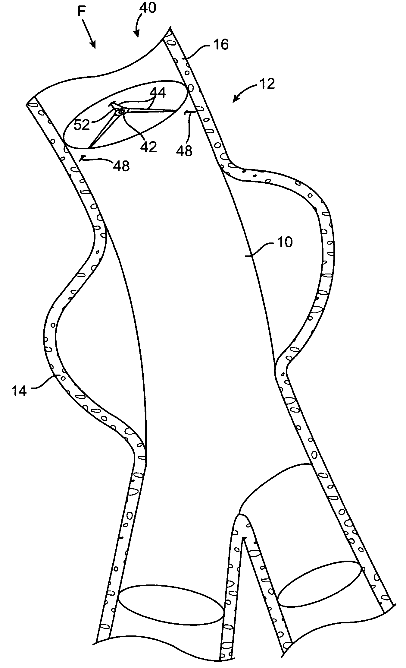
  • Claims
  • Application Information

AI Technical Summary

Benefits of technology

[0008] The present invention generally concerns methods and apparatus for the placement and securement of intraluminal devices, such as a stent graft, in a body flow lumen location with minimal risk of endoleak and minimal risk of migration of the device from the intended location to an additional location in the lumen. In one embodiment, the invention includes an intraluminal exclusion device (exclusion device), such as a stent graft, having an outer cylinder-like wall which is located to span the location of a luminal risk factor, such as an aneurysm, and a securement device deployable to extend through the stent graft wall and into the blood vessel wall, to secure the stent graft to the blood vessel wall. The securement device may be placed in the body flow lumen at the time of intraluminal exclusion device placement or at some time thereafter where risk of intraluminal exclusion device migration becomes apparent. Additionally, the securement device may be used in conjunction with a device or material other than an intraluminal exclusion device, such as a device intended for the time release of therapeutic agents to the aneurysmal site, or may include such a delivery device formed therewith.
[0009] In a further embodiment, the securement device is provided, and includes at least one anchor portion extending from a main body portion. The anchor portion extends through the intraluminal exclusion device wall and into the flow lumen wall there adjacent. The securement device, in one embodiment, includes at least three anchor portions extending from a main body portion, where at least one of the anchor portions has a tip that is configured to pierce the intraluminal exclusion device and flow lumen wall with a limiter extending therefrom that is configured to bear against the inner surface of the intraluminal exclusion device and thereby limiting the penetration depth of the anchor into the blood vessel wall. In a still further embodiment, the securement device deploys without the need for extensive manipulation of a catheter or tube. Instead, upon release from the tube or catheter at the deployment location, the anchor portion of the securement device is deployed adjacent to its final anchoring position, i.e., adjacent the blood vessel wall, simply upon release thereof from the catheter or tube. Alternatively, the anchor portion of the securement device may be deployed through the simple inflation of a balloon. Thus, the securement device may be deployed without the need for excessive twisting and manipulation of a catheter or tube from a position remote from the securement device deployment position. Once the securement device is deployed and position, in one embodiment, it is anchored into the blood vessel wall by the simple act of pulling on a wire detachably connected therewith.

Problems solved by technology

This treatment regimen is highly invasive for the patient undergoing it, and typically requires a multiple day post-operative hospital stay, as well as several months of recovery time until the patient has fully recovered from the surgery.
Additionally, some patients may not be capable of undergoing such a procedure.
Despite the intended expansion and sealing capability of the stent graft to the blood vessel wall, it is still possible, on occasion, for the stent graft to become dislodged or improperly sealed against the blood vessel wall.
In such a case, fresh blood will reach the weakened aneurysmal wall location, creating a renewed risk that the blood vessel may rupture.
Furthermore, if the stent graft is inadequately engaged against the blood vessel wall, such that the seal with healthy tissue is lost, it may migrate.
This process is both cumbersome and time consuming.
Additionally, the placement of such hooks can distort the stent graft, as hook placement through the stent graft may be angled and therefore not, circumferentially, match the subsequent placement of the hook in the blood vessel wall.
This can create a distortion about the circumference of the stent graft, thereby reducing the sealing capability of the stent graft allowing the leakage of blood into the aneurysmal location.

Method used


Image

  • Intravascular securement device
  • Intravascular securement device
  • Intravascular securement device

Examples


Embodiment Construction

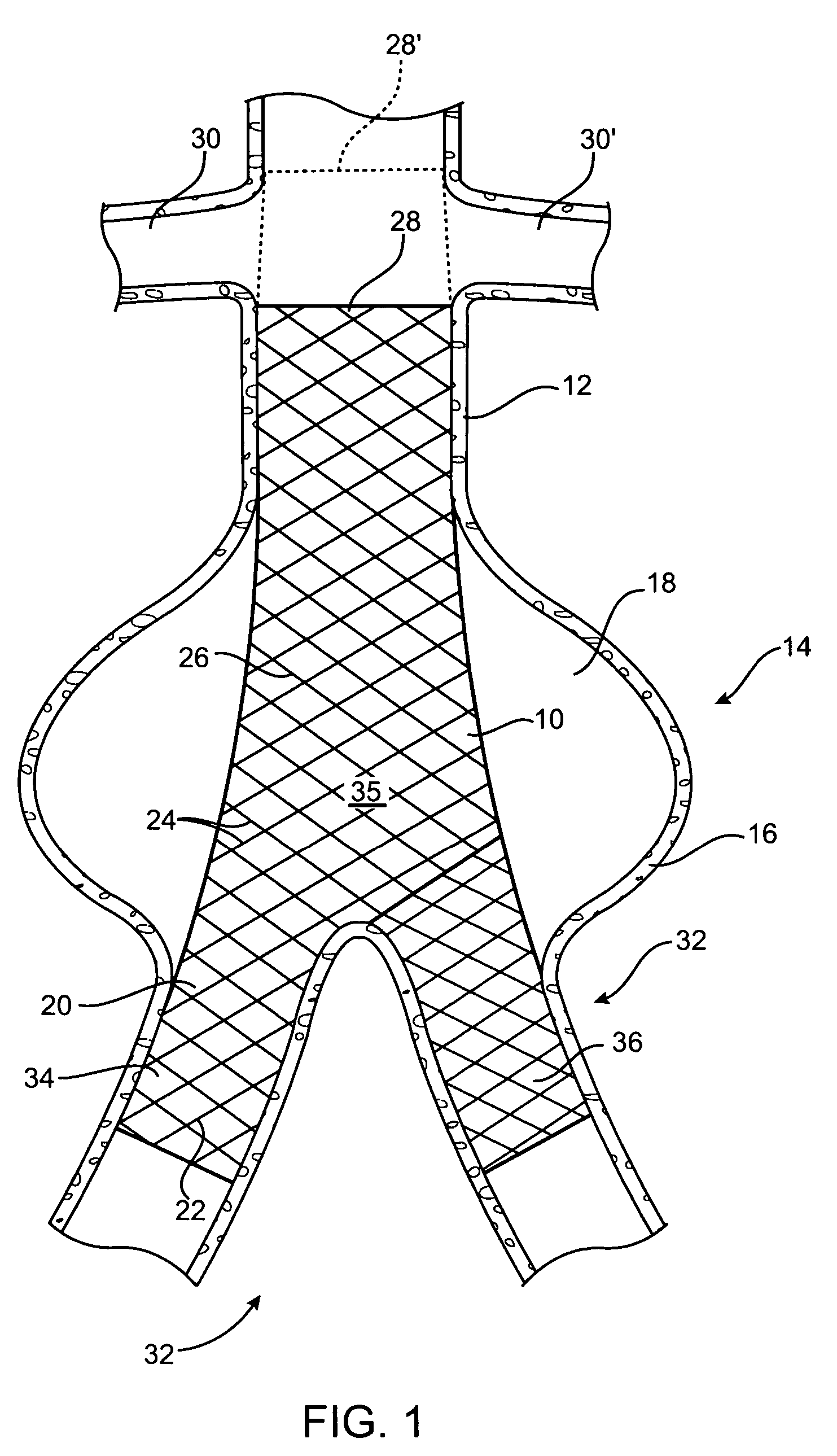
[0026] Referring initially to FIG. 1, there is shown an intravascular repair vehicle, specifically a stent graft 10, positioned in a blood vessel, in this embodiment, the descending abdominal aorta 12, and spanning, within the aorta 12, an aneurysmal portion 14 of the aorta 12. The aneurysmal portion 14 is formed of a bulging of the aorta wall 16, in a location where the strength and resiliency of the aorta wall 16 is weakened. As a result, an aneurysmal sac 18 is formed of distended vessel wall tissue. The stent graft 10 is positioned spanning the sac 18 and thereby both provides a secure passageway for blood flow through the aorta 12 and seals off the aneurysmal portion 14 of the aorta 12 from contact with further blood flow through the aorta 12. The stent graft 10 further includes a graft portion 20, which is configured from a biocompatible fabric, and which is sewn or otherwise attached to stent portion 22, which is shown as a plurality of wires 24 interleaved into a mesh 26 pat...


PUM


Abstract

A method and apparatus for a securement device useful for the treatment of aneurysms includes a hub and, in one aspect, a plurality of arms or spikes in a star pattern extendable therefrom and into engagement with a blood vessel wall. The securement device may be deployed to anchor a secondary device, such as an exclusion device for example a stent graft, in position in a flow lumen and thereby prevent the migration of the exclusion device in the flow lumen. The arms may be positioned to penetrate through the exclusion device and thence into the flow lumen wall to provide such securement.

Description

BACKGROUND OF THE INVENTION [0001] 1. Field of the Invention [0002] Embodiments of the present invention generally relate to the field of the treatment of body lumens, more particularly to the field of the treatment of blood vessels, and more particularly to the treatment of blood vessel aneurysms with intraluminal devices such as stents, lined stents such as stent grafts, and the use of a securement device therewith to secure the intraluminal device in an intended position within the blood vessel. [0003] 2. Description of the Related Art [0004] Aneurysm, i.e., the enlargement of a blood vessel at a specific location therein to the point where rupture of the blood vessel is imminent, has been treated in the past by surgical intervention techniques, whereby the affected portion of the blood vessel is removed, or bypassed, so that a synthetic graft replaces the flow lumen. This treatment regimen is highly invasive for the patient undergoing it, and typically requires a multiple day po...

Claims


Application Information

Patent Timeline
Patent Type & Authority Applications(United States)
IPC IPC(8): A61F2/06
CPCA61F2/064A61F2/07A61F2002/065A61F2230/005A61F2/90A61F2002/075A61F2220/0016
Inventor CHU, JACK
Owner MEDTRONIC VACULAR
Learn More